Continue to Site

Welcome to EDAboard.com

Welcome to our site! EDAboard.com is an international Electronics Discussion Forum focused on EDA software, circuits, schematics, books, theory, papers, asic, pld, 8051, DSP, Network, RF, Analog Design, PCB, Service Manuals... and a whole lot more! To participate you need to register. Registration is free. Click here to register now.

20KHz Instrumentation Amplifier

Status
Not open for further replies.

pal114525

Member level 5
Joined
May 20, 2015
Messages
87
Helped
0
Reputation
0
Reaction score
0
Trophy points
6
Activity points
717
Hi,

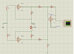
I've designed an Instrumentation amplifier to receive a 20KHz signal from another coil at the Tx side such that this would give ZERO output if there is NO METAL between the TX and RX. And this would give an output voltage if there is any metal in between TX and RX.
Would you please guide me to select the proper values of resistor for that?

Thanks & Regards.
 

Attachments

  • Instru_ampr.png
    Instru_ampr.png
    53.4 KB · Views: 128

Hi,

The resistors depend on gain. Gain is V_out / V_in. You don't give those values. So it is impossible to calculate.
****

Why don't you just connect both coils in series?
If you want to subtract both signals you just have to flip one coil.

Klaus
 

Hi,

Thanks for your valuable feedback.
How can I flip one coil?

Thanks & Regards.
 

Hi,


Change both connections of the coil.

Klaus

RX_coil.png

Hi,

The attached schematic is a typical instrumentation amplifier.
This circuit should cancel out any emf induced in the coils such that the emfs are equal in magnitude.
The two coils have the same inductance (1.7mH).
The Transmitter (Tx, which is not shown here) is transmitting an EM field of 16KHz continuously. The two RX coils are geometrically
placed such that they should cancel out this field and at the output of the instrumentation amplifier there should be ZERO volt ac signal.
Would you please tell me if any changes are required in the circuit?

Thanks & Regards.
 

Instrumentation amplifier inputs must not float.

Hi,

Thanks for your valuable feedback.
Would you please tell me the change required for that?

Thanks & Regards.

- - - Updated - - -

Hi,

Thanks for your valuable feedback.
Would you please tell me the change required for that?

Thanks & Regards.

Please see the attachment for the coils placement.RX_geometry.png
 

Hi,

with two coils anti series, are you sure you need an amplifier?

The given LT1167 circuit gives gain of 6. This could be done with a simple 0.30€ OPAMP instead of the 10€+ LT1167.
Just use non inverting OPAMP setup.

Klaus
 

Hi,

with two coils anti series, are you sure you need an amplifier?

The given LT1167 circuit gives gain of 6. This could be done with a simple 0.30€ OPAMP instead of the 10€+ LT1167.
Just use non inverting OPAMP setup.

Klaus

Hi,

Thanks for your valuable feedback.
Would you be kind to explain me the following point?
How Vin would be connected in that case.
I have two terminals of the coils left. Where these two terminals would be connected?

Thanks & Regards.
 

Hi,

Would you be kind to explain me the following point?
How Vin would be connected in that case.
I have two terminals of the coils left. Where these two terminals would be connected?

Two coils. Each has two connections, one with a dot one without dot.
-> One coil (no dot) connect to GND.
-> both coils (dot) connect together.
-> other coil (no dot) is signal output (difference of coil1 - coil2)

Klaus

- - - Updated - - -

Hi again.

This circuit should cancel out any emf induced in the coils
--> EMF cancelled out = zero

The Transmitter (Tx, which is not shown here) is transmitting an EM field of 16KHz continuously. The two RX coils are geometrically
placed such that they should cancel out this field and at the output of the instrumentation amplifier there should be ZERO volt ac signal.
--> 16kHz cancelled out = zero

I wonder what signal you expect at the output. You only tell it is zero.

Klaus
 

i think the OP has something related to this in his mind.

https://en.wikipedia.org/wiki/Magnetic_induction_tomography

He might be trying to measure a secondary field which is out of phase from the primary field; the secondary field is induced by eddy currents induced when a metallic object is place between the transmitting and receiving coil. The magnitude of this secondary field seems to be very low therefore requiring a instrumentation amplifier.
 

Hi,


Two coils. Each has two connections, one with a dot one without dot.
-> One coil (no dot) connect to GND.
-> both coils (dot) connect together.
-> other coil (no dot) is signal output (difference of coil1 - coil2)

Klaus

- - - Updated - - -

Hi again.


--> EMF cancelled out = zero


--> 16kHz cancelled out = zero

I wonder what signal you expect at the output. You only tell it is zero.

Klaus

Hi,

I am using TL084 as a non-inverting amplifier as you have mentioned above.
I am getting a triangular wave signal at the output of the amplifier.
Would you please tell me how to make it to zero?

Thanks & Regards.
 

Hi,

triangular. Can´t imagine why triangular.

You used no capacitor except the ones in the supply lines?

What frequency? Is it the 16 kHz of your transmitter? Maybe the transmitter causing this triangular waveform.
Use a scope and - if possible - measure the signal of both coils at the same time. Best if the voltage is referenced to the joint point of both coils.

Also a waveform of the transmitter coil current could give information.

How to make it zero: Both coils same amplitude and same phase then the difference is zero.

Klaus

Hi,

Thanks for your valuable feedback.
The freq. of the triangular wave is ~350KHz and amplitude is 10V.
Actually, I've switched off the Tx side and only Receiver side is switched ON which is basically a non-inverting amplifier using TL084.
I am getting a triangular wave output from the amplifier.

Thanks & Regards.
 

The datasheet of a TL084 shows that its output slew rate does not pass a frequency higher than about 100kHz. Its slow slewing causes a triangle waveform.
Also, at 350kHz its voltage gain without any negative feedback is only about 10 so its distortion is very high.

EDIT: With the transmitter turned off the output of the receiver has a triangle wave? Then the receiver is oscillating.

Hi,

Would you please tell me the solution for it?

Thanks & Regards.
 

Is the receiver oscillating at 350kHz? If it is then please post your schematic and I hope it is not built on a solderless breadboard, is it?
 

Is the receiver oscillating at 350kHz? If it is then please post your schematic and I hope it is not built on a solderless breadboard, is it?

RX_TL084.png

It is built on a breadboard.

Thanks & Regards.

- - - Updated - - -

RX_TL084.png

It is built on a breadboard.

Thanks & Regards.
The coil arrangements are as belows:

1. Start terminal of the 1st coils is GND
2. End terminal of the 1st coil is connected to END terminal of the 2nd coil
3. Start terminal of the 2nd coil is connected to the non-inverting terminal.
 

Hi,

The given LT1167 circuit gives gain of 6.

Your circuit now shows a gain of 1000. This is a totally different situation!

Now it is clear where the triangle comes from: by picking up some noise and the gain of 1000 the Opamp is completely over driven and what you see is the fall time and rise time limit of the Opamp.

Use a smaller gain setup.

Klaus
 

Hi,


Your circuit now shows a gain of 1000. This is a totally different situation!

Now it is clear where the triangle comes from: by picking up some noise and the gain of 1000 the Opamp is completely over driven and what you see is the fall time and rise time limit of the Opamp.

Use a smaller gain setup.

Klaus

Hi,

Now I am using a gain of 6 as R1 = 10K and R2 = 2K. But, I am still getting triangular wave at the output.
Please let me know how overcome this error.

Thanks & Regards.
 

Status
Not open for further replies.

Similar threads

Part and Inventory Search

Welcome to EDABoard.com

Sponsor

Back
Top