rezaxyz
Junior Member level 2
Hi all,
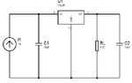
In your opinion is it possible to use a constant current source (i.e. LED Driver) as a digital circuit power supply (like attached schematic)? current source specification: Pout=3W, Isc=200 mA, Voc=20v and the desired regulated voltage is 5V, 100mA.
Thank in Advance,
Reza
In your opinion is it possible to use a constant current source (i.e. LED Driver) as a digital circuit power supply (like attached schematic)? current source specification: Pout=3W, Isc=200 mA, Voc=20v and the desired regulated voltage is 5V, 100mA.
Thank in Advance,
Reza