Continue to Site

Welcome to EDAboard.com

Welcome to our site! EDAboard.com is an international Electronics Discussion Forum focused on EDA software, circuits, schematics, books, theory, papers, asic, pld, 8051, DSP, Network, RF, Analog Design, PCB, Service Manuals... and a whole lot more! To participate you need to register. Registration is free. Click here to register now.

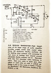
Low level AM Transmitter Circuit and little description.

Status
Not open for further replies.
Lambda ? it is wave distance . it will given from the formula :( 3*10^8)/F it is according to the meter . an example : consider you want transmit 27 MHZ , sine wave . it's lambda , is 3*10^8/27*10^6=11 meter
So , if you use an image reflected antenna ( lambda/4 ) it's dimension will be 11/4 =2.75 meter . it will be just a wire . but if you use dipole antenna , lambda/2 you will have two wire . first one is ground and the other one is out put . distance of your antenna will be 11/2=5.5 meter . it means two wire with 2.75 meter size . or each other kind of antenna ! but for transmitters at high powers , and frequency of HF band , most of the time , most reasonable choice is lambda/2 antenna .
Nice information. I don't know anything about lambda, but I know lambda is a wavelength.

( didn't you have telecommunications in university ? or perhaps didn't you read any book regarding this issue ever ?)
I have read. But we didn't cover this topic yet in our course.

Which resistor you are referring to ?
All resistors used in zsolt1's circuit.

High level transmitters will have supplies higher than that . for example a transmitter with power of 200 watt is high level . or for instance , a transmitter with power of 800 KW . it is high level and it's design steps are completely different .
OK. Thanks for this.

Can you tell me how to determine the range of the transmitter by calculations. I want to determine the range of zsolt1's circuit.

Thank you goldsmith
 

hi,
I can't provide info about the oscilator because i never bothered about it... indeed the feedbeck loop seams to be missing and that is not ok. I can tell more about the circuit i built only on saturday when i get home and i can take a look at the circuit (maybe i will take photo about it) . If you do not trust the oscilator just replace it with any colpitts oscilator from the internet or from people on this forum. It will work 100% guarnteed , about it's range you have to test it.. one thing is certain : if you increse the power on the output the range will increse to . in order to do that you can go to the limits of the BC 548 transistor or simply attach a RF power amplifier stage, let's say about 1 W between the circuit and the antenna. About the antenna , just use a simple wire at the beginig, after setup you can experiment with special antennas

- - - Updated - - -

Ps: lambda is the wawe length ; lambda = speed of light / frequency = 300 000 / f ; if f is in [Hz] -> lambda in [m] . In principal you can calculate the wave length you are transmitting and than you use a wire for the antenna that has the fizical length of 1, 1/2 or 1/4 of the calculated wave length ........ i belive . Do some reserch about it to be shore
 
Last edited:

All resistors used in zsolt1's circuit.
I don't think that they are high wattages !
Can you tell me how to determine the range of the transmitter by calculations. I want to determine the range of zsolt1's circuit.
Range ? range of power or range of frequency ?
 

I can't provide info about the oscilator because i never bothered about it... indeed the feedbeck loop seams to be missing and that is not ok. I can tell more about the circuit i built only on saturday when i get home and i can take a look at the circuit (maybe i will take photo about it) .
So you are saying feedback loop seems to be missing and that is not OK. Does this circuit has problem? If so, then kindly tell me the solution. Tell me please.

If you do not trust the oscilator just replace it with any colpitts oscilator from the internet or from people on this forum. It will work 100% guarnteed ,
I trust oscillator. You said that when you tested this circuit, it worked. So therefore I trust too. Should I need to be replaced the oscillator circuit still?

I don't think that they are high wattages !
You mean they could be quarter watt?

Range ? range of power or range of frequency ?
Range of the transmitter. how far it can be heard?
Well zsolt1 told, we have to test it in order to determine the range.

- - - Updated - - -

Can anyone tell me what is the frequency of the oscillator in the circuit given by zsolt1?
And also the output frequency of that circuit?
 

@godlsmith can you help me with zsolt1's circuit?
No, he can't. Goldsmith likes to write as if he is an engineer with many years experience. In truth, he is a young student who knows only a little about electronics. He does not understand zsolt1's circuit. If he did, he would have said something useful before now.

BTW: all the resistors can be 1/4W or any higher power rating. If you look closely, you will see that goldsmith could not even give a clear answer to that question.
 

all the resistors can be 1/4W or any higher power rating.
Thank you for answer.

If you look closely, you will see that goldsmith could not even give a clear answer to that question.
I agree with you.

Can you answer my other questions too?
 

You mean they could be quarter watt?
Very unlikely. The available RF power will be in a 10 mW order of magnitude. But when connected to an electrical short antenna (as unavoidable for the said 350 to 1000 kHz frequency range), there won't be more than µW radiated. The second link in post #19, tries a rough estimation of radiated power. (the circuit is already using a simple kind of impedance matching and can be expected to be better than the present one in this regard).

But even very low µW levels can be sufficient to achieve the intended transmission range. Reviewing the present discussion, I fear that antenna matching goes beyond the scope of your project.

P.S.: I realize that quarter watt meaned resistor power. goodfreyl is right about this point of course.
 

hi,
the transmitter works nowdays to . What i wanted to say is that there is a posibility that the oscillator is not correctly drawn because i made the drawing from memory (since i am not home for the week) . I suggested to replace the oscillator just in case you do not have the time to wait until (saturday) i can provide exact info about the transmiter i built in the far past.
Generally i am speaking from memory about this transmiter, and i forgot a lot so critics are accepted :)
All rezistors are 0.5W. The frequency is closely approximated with Thomson formula ...
Ps: I also suggest to keep eyes open for other projects to so that you can try many ways
 

Zsolt1's design
79608d1346686405-photo0547.jpg


is simple if you have the right inductors and variable capacitors. If you have no idea where to get them ( what resources do you have?) you won't get it to work.

The two inductors must be in a can as they are mutually coupled as a transformer. ( salvage from an old radio?) Similarly you need twin variable capacitors stripped from an old radio. You will need an RLC meter to verify the parts.

The 100pF gate cqap. is used to provide negative feedback to make it oscillate and regulate the amplitude of the sine wave.

Other designs that use a simple discrete LC oscillator will be easier to get working at the right frequency in the AM radio band as this one. LC Values will be in a similar order of magnitude..

It all depends on your ability to find parts since there is no easy way to identify a part number and a supplier.

Unless you tell us what resources you have for parts and what skills you have for making a tiny circuit with possible shielding required, so that stray noise is reduced., it is hard to help you succeed.
 
Last edited:
  • Like
Reactions: FvM

    FvM

    Points: 2
    Helpful Answer Positive Rating
I suggested to replace the oscillator just in case you do not have the time to wait until (saturday) i can provide exact info about the transmiter i built in the far past.
Although I don't have much time. But I still want you to provide me exact information with exact circuit diagram till Saturday as you said above.

So if I replace the oscillator with colpitts oscillator then it should working fine, huh?
But I don't know what should be values of components used in colpitts oscillator for this components. And I don't know how to calculate. Therefore I am unable to use any other substitution in the circuit. I have to submit proposal with this one :-(
But I am happy, at least I have something to propose it to my teacher.

Thanks for useful information given by zsolt1, FvM and SunnySkyguy :)

- - - Updated - - -

The output power of this transmitter is 10mW?
 

I agree that the FET circuit should be seen as a hartley oscillator with coupled inductors. IMHO it's the only plausible circuit explanation. In the usual form with closely coupled coils, the right feedback coil would be made with 1/4 or even less of the left coil. Annotating the coils with apparently equal "L" suggests a more loose coupling.
 

I agree that the FET circuit should be seen as a hartley oscillator with coupled inductors. IMHO it's the only plausible circuit explanation. In the usual form with closely coupled coils, the right feedback coil would be made with 1/4 or even less of the left coil. Annotating the coils with apparently equal "L" suggests a more loose coupling.
So should I replace this Oscillator circuit?
 

Although the circuit looks a bit unusual, it can be expected to work. In so far I agree with zsolt1.

It's not exactly clear for me which components are at reach for your design, e.g. a FET? Designing with single or coupled inductors implies that you know how to calculate it, or a possibly able to test it, etc.
 

So don't you give me a substitution instead that one which is in the diagram?
Can't you provide me a circuit with full calculated values? (A colpitts oscillator)
 

I read bits of this thread just now, and don't want to detract from the discussion, if a circuit has already been discussed.
But I got curious to see if an old book 'Electonic Circuits Manual' by John Markus had any such circuits (I always refer to it
for ancient circuits.
It had the attached one. It doesn't specify winding for L1, but I suppose any ferrite rod with 50 or so turns would be
in the right ballpark, from AM radio construction memory. It doesn't mention where to take the tap (it is a hartley osc), but
I suppose if it was scraped enamel copper wire at a few points then it could be experimented until it oscillated.
Anyway, sorry for interrupting the existing thread - it is just another circuit that I thought maybe was worth sharing anyway.
am_tx.jpg
 
  • Like
Reactions: zsolt1

    zsolt1

    Points: 2
    Helpful Answer Positive Rating
So don't you give me a substitution instead that one which is in the diagram?
The first transmitter circuit that FvM showed in this post contains a nice simple oscillator. Actually, don't understand why you didn't want to use that circuit.
 
Hi Godfreyl
No, he can't. Goldsmith likes to write as if he is an engineer with many years experience. In truth, he is a young student who knows only a little about electronics. He does not understand zsolt1's circuit. If he did, he would have said something useful before now.
Well i think you are an oracle ! because you can judge instead of each people that you didn't see him/her from near ! are you really an oracle ? if yes tell us when this world coming end ?!!
It is correct that i'm young but i have many experiences in HF transmitter design . because it is around 9 years that i'm studying electronics ! under guidance of old professors and old engineers and of course some peoples younger than that ! it is how i have earned these experiences .
My friend before you write here , you could ask from me . isn't it ? and another thing is there any problem between us ? i think it is ? because most of the times your behavior isn't politely instead of me , and most of the times your words are impolite . can you tell me the reason ?
However i don't need to demonstrate you my abilities and i don't need to talk you regarding my job .
Regards
Goldsmith
 

Hi Godfreyl

Well i think you are an oracle !
No, but I can read. You wrote here that you are a university student and that you were born in 1992.

i have many experiences in HF transmitter design . because it is around 9 years that i'm studying electronics ! under guidance of old professors and old engineers and of course some peoples younger than that !
As I said; you write as if you have many years experience.

However less than one year ago you started this thread because you did not know how to design a one transistor CE amplifier, and you started this thread because you could not understand a simple circuit with just one opamp and four resistors.

That is why I said you know only a little about electronics. I think those two examples are enough to make the point.
 
Last edited:

@ goldsmith

How are you?

I need your help.

@ zsolt1
Hi

In post#48 you said that you would post your complete circuit by saturday, do you remember?
 

Status
Not open for further replies.

Part and Inventory Search

Welcome to EDABoard.com

Sponsor

Back
Top