munzir
Full Member level 6
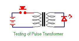
How to test a pulse transformer which is used in the VFDs (inverters) ? whether three phase output or a single phase output .........
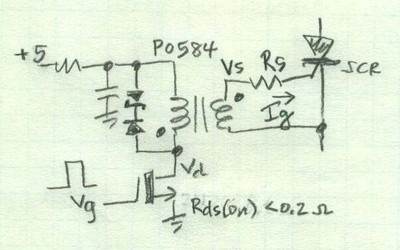
How can i get to know that the pulse transformer is working and its firing the pulses at the gate of the SCR ?
thanks
How can i get to know that the pulse transformer is working and its firing the pulses at the gate of the SCR ?
thanks