Continue to Site

Welcome to EDAboard.com

Welcome to our site! EDAboard.com is an international Electronics Discussion Forum focused on EDA software, circuits, schematics, books, theory, papers, asic, pld, 8051, DSP, Network, RF, Analog Design, PCB, Service Manuals... and a whole lot more! To participate you need to register. Registration is free. Click here to register now.

[SOLVED] PPIC16F877 (MPASM, MPLINK) - Proteus ISIS Simulation : USART Module not working

Status
Not open for further replies.

zia.newversion

Member level 5
Joined
Mar 28, 2010
Messages
83
Helped
1
Reputation
2
Reaction score
1
Trophy points
1,288
Location
Pakistan
Activity points
2,188
Hi there.
So...

I am back again with another problem. Here is the code (asm).
The purpose of the program to transmit the data on a parallel port to USART TX line (using built in module - NOT manual implementation of USART).
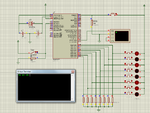
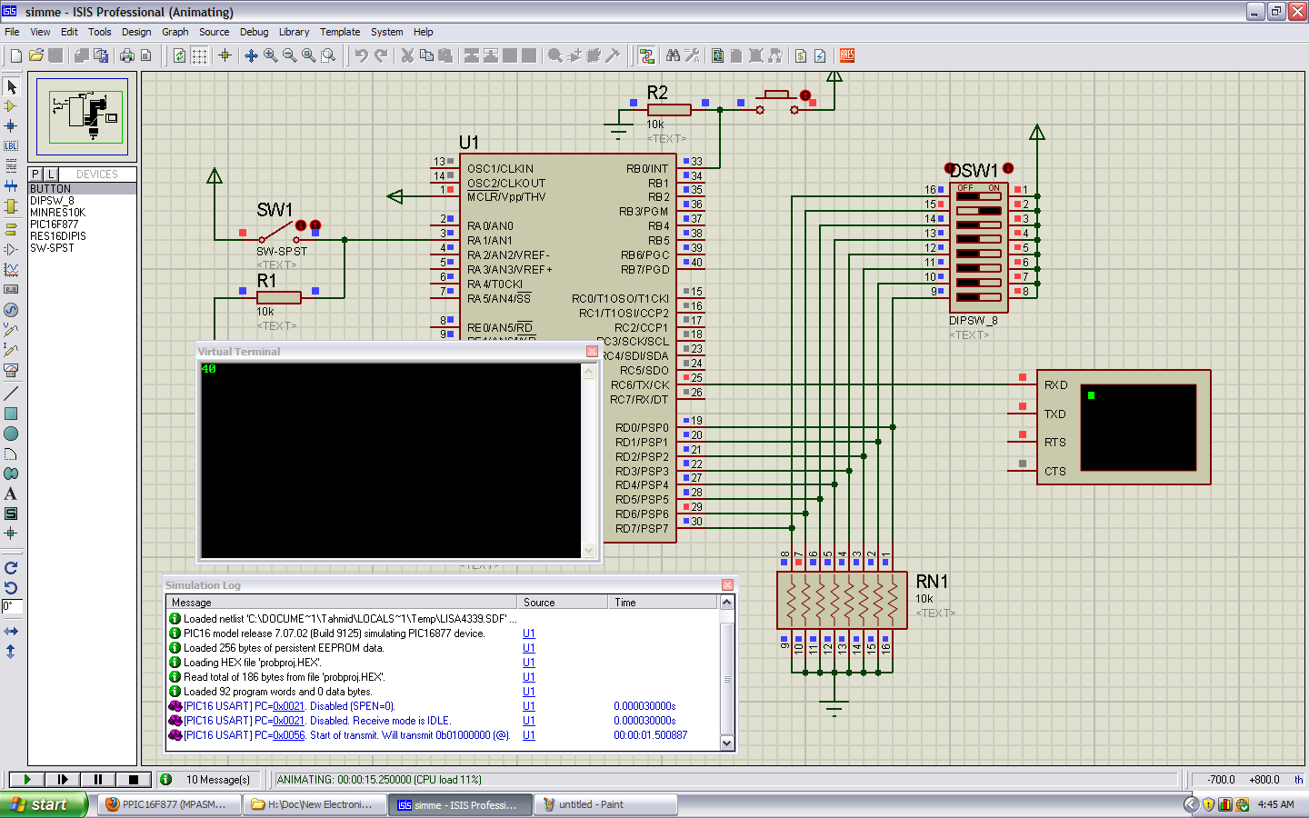
There will be a DIP switch on PORTD in my conceived hardware model, with LED on switch to indicate if it is on or off. There will be MAX232 or relevant on USART outputs (but Proteus does not require it AFAIK).
In addition to that, there will be a selection switch on RA1, which will be used by controller to decide whether to use automatic or manual transmission modes.
In automatic mode, the controller automatically transmits whatever is on PORTD when a TMR0 interrupt occurs (which it does very frequently). This mode is useful when taking sampled data from an external ADC, for example. In manual mode, the controller will require a hardware INT or RB0/INT to be provided for it to start tranmission.

And that's that. The code:


Code ASM - [expand]
1
2
3
4
5
6
7
8
9
10
11
12
13
14
15
16
17
18
19
20
21
22
23
24
25
26
27
28
29
30
31
32
33
34
35
36
37
38
39
40
41
42
43
44
45
46
47
48
49
50
51
52
53
54
55
56
57
58
59
60
61
62
63
64
65
66
67
68
69
70
71
72
73
74
75
76
77
78
79
80
81
82
83
84
85
86
87
88
89
90
91
92
93
94
95
96
97
98
99
100
101
102
103
104
105
106
107
108
109
110
111
112
113
114
115
116
117
118
119
120
121
122
123
124
125
126
127
128
129
130
131
132
133
134
135
136
137
138
139
140
141
142
143
list    p=16f877
        #include "p16f877.inc"
 
; LP Oscillator between OSC1 OSC2 pins
; Watchdog timer is off
; All code protection is off
; Brown-Out Reset is enabled
; EEPROM data protection is off
; Write to EEPROM enabled
; ICD is off, RB6 and RB7 are GPIO
        __config        _LP_OSC & _WDT_OFF & _PWRTE_ON & _CP_OFF & _BODEN_ON & _LVP_OFF & _CPD_OFF & _WRT_ENABLE_ON & _DEBUG_OFF
 
org     0x0000
_resetv
        call    _boot
        goto    _main
 
org 0x0004
_intv
        goto    _isr
 
org     0x0010
_boot
; Disable pullups                                                       B7=1
; Interrupt on rising edge                                      B6=1
; TMR0 runs on internal instruction cycle       B5=0
; TMR0 increments on low-high transition        B4=0
; Prescalar 1:2 assigned to TMR0                        B3=0 <B2:B0>=000 (Overflow time = 2 x 256 x Tosc)
        banksel OPTION_REG
        movlw   0xC0
        movwf   OPTION_REG
 
; Disable all interrupts
; Clear all interrupt flags
        banksel INTCON
        clrf    INTCON
 
; Disable all peripheral interrupts
; Clear all peripheral interrupt flags
        banksel PIE1
        clrf    PIE1
        clrf    PIE2
        banksel PIR1
        clrf    PIR1
        clrf    PIR2
 
; Disable ADC module by clearing ADCON0 and ADCON1
        banksel ADCON0
        clrf    ADCON0
        banksel ADCON1
        movlw   0x06
        movwf   ADCON1
 
; We are transmitting at 9600 baud/s with LP Oscillator @ 4MHz
; To set a Baud Rate of 9.6 Kbdps, SPBRG should be initialized with 25(decimal)
        banksel SPBRG
        movlw   0x19
        movwf   SPBRG
; We are using asynchronous serial tranmission (RS232)
; For that, SYNC bit of TXSTA must be cleared
        bcf             TXSTA, SYNC
; Just because datasheet says so, enable SPEN
        banksel RCSTA
        bsf             RCSTA, SPEN
; Finally, enable the transmitter by setting TXEN
; Enabling transmitter now will ensure nothing goes wrong in _main sub
        banksel TXSTA
        bsf             TXSTA, TXEN
 
        return
 
_main
; Make all ports output
; Even if we don't have to use all of them.
        banksel TRISA
        clrf    TRISA
        clrf    TRISB
        clrf    TRISC
        clrf    TRISE
; Make TRISD input. That is our dip-switch parallel input port.
        movlw   0xFF
        movwf   TRISD
; Make RA1 input
; This pin will be used by user to set automatic/manual transmission modes.
        bsf             TRISA, RA1
; In automatic mode, controller transmits after every TMR0 overflow interrupt.
; In manual mode, external hardware interrupt (RB0) must be activated to transmit.
        
 
; Clear all ports
        banksel PORTA
        clrf    PORTA
        clrf    PORTB
        clrf    PORTC
        clrf    PORTD
        clrf    PORTE
 
; Enable interrupts globally
        banksel INTCON
        bsf             INTCON, GIE
 
_loop
; RA1 enabled = automatic mode | RA1 disabled = manual mode
; In automatic mode, controller transmits after every TMR0 overflow interrupt.
; In manual mode, external hardware interrupt (RB0) must be activated to transmit.
        banksel PORTA
        btfss   PORTA, RA1
        goto    _sthint
        goto    _sttint
        goto    _loop
 
_sthint
; Set hardware interrupt and clear timer interrupt
        banksel INTCON
        bcf             INTCON, T0IE
        bsf             INTCON, INTE
        goto    _loop
 
_sttint
; Set timer interrupt and clear hardware interrupt
        banksel INTCON
        bcf             INTCON, INTE
        banksel TMR0
        clrf    TMR0
        bsf             INTCON, T0IE
        goto    _loop
        
 
_isr
        call    _tx
; Like always, clear flags before exiting ISR otherwise the program will keep looping in ISR
        banksel INTCON
        bcf             INTCON, INTF
        bcf             INTCON, T0IF
        retfie
 
_tx
        banksel PORTD
        movf    PORTD, W
        return                                  ; TRMT is enabled, TSR is empty, tranmission completed - Return from routine
        
        
end


I have revised the code many times so as not to mickey myself out because of some silly mistake. It seems (to me) there is no silly mistake. However, there is no guarantee. :p

In any case, the ISIS simulation files and MPLAB project files are attached. If anyone could look into what is causing the problem, I shall be duly grateful.

P.S. I know the algorithm has some design flaws. I did not have time to re-evaluate my approach. So I am posting it as is. I shall be making changes to the algorithm (_sthint and _sttint are placed at awkward positions, I was thinking more like enabling both INT and TMR0 interrupts, and then polling them in ISR). But apart from that, if I could make this one work, I shall be able to optimize and remove the design or approach flaws later.
 

Attachments

  • f877-p2s.zip
    33.1 KB · Views: 83

I've changed a lot in the code. It's kinda messy, but I fixed the errors. :smile:

Code:
	list	p=16f877
	#include "p16f877.inc"

; LP Oscillator between OSC1 OSC2 pins
; Watchdog timer is off
; All code protection is off
; Brown-Out Reset is enabled
; EEPROM data protection is off
; Write to EEPROM enabled
; ICD is off, RB6 and RB7 are GPIO
	__config	_XT_OSC & _WDT_OFF & _PWRTE_ON & _CP_OFF & _BODEN_ON & _LVP_OFF & _CPD_OFF ;& _WRT_ENABLE_ON & _DEBUG_OFF

org	0x00
_resetv
	goto	_boot

org 0x04
_intv
	goto	_isr

;org	0x0010
_boot
; Disable pullups							B7=1
; Interrupt on rising edge					B6=1
; TMR0 runs on internal instruction cycle	B5=0
; TMR0 increments on low-high transition	B4=0
; Prescalar 1:2 assigned to TMR0			B3=0 <B2:B0>=000 (Overflow time = 2 x 256 x Tosc)
	banksel	OPTION_REG
	movlw	0xC0
	movwf	OPTION_REG

; Disable all interrupts
; Clear all interrupt flags
	banksel	INTCON
	clrf	INTCON

; Disable all peripheral interrupts
; Clear all peripheral interrupt flags
	banksel PIE1
	clrf	PIE1
	clrf	PIE2
	banksel	PIR1
	clrf	PIR1
	clrf	PIR2

; Disable ADC module by clearing ADCON0 and ADCON1
	banksel ADCON0
	clrf	ADCON0
	banksel	ADCON1
	movlw	0x06
	movwf	ADCON1

; We are transmitting at 9600 baud/s with LP Oscillator @ 4MHz
; To set a Baud Rate of 9.6 Kbdps, SPBRG should be initialized with 25(decimal)
	banksel	SPBRG
	movlw	.6
	movwf	SPBRG
; We are using asynchronous serial tranmission (RS232)
; For that, SYNC bit of TXSTA must be cleared
	movlw	0x20
	movwf	TXSTA
	banksel	RCSTA
	movlw	0x80
	movwf	RCSTA
; Finally, enable the transmitter by setting TXEN
; Enabling transmitter now will ensure nothing goes wrong in _main sub

_main
; Make all ports output
; Even if we don't have to use all of them.
	banksel PORTA
	clrf	PORTA
	clrf	PORTB
	movlw	0xFF
	movwf	PORTC
	clrf	PORTE

	banksel TRISA
	movlw	0x02
	movwf	TRISA
	movlw	0x01
	movwf	TRISB
	movlw	0xFF
	movwf	TRISC
	clrf	TRISE
; Make TRISD input. That is our dip-switch parallel input port.
	movlw	0xFF
	movwf	TRISD

; Make RA1 input
; This pin will be used by user to set automatic/manual transmission modes.
; In automatic mode, controller transmits after every TMR0 overflow interrupt.
; In manual mode, external hardware interrupt (RB0) must be activated to transmit.

; Enable interrupts globally
	banksel	INTCON
	bsf		INTCON, GIE

_loop
; RA1 enabled = automatic mode | RA1 disabled = manual mode
; In automatic mode, controller transmits after every TMR0 overflow interrupt.
; In manual mode, external hardware interrupt (RB0) must be activated to transmit.
	banksel	PORTA
	btfss	PORTA, 1
	goto	_sthint
	goto	_sttint
Check
	btfss	PIR1, TXIF
	goto	$-1
	bcf		PIR1,TXIF
	goto 	_loop

_sthint
; Set hardware interrupt and clear timer interrupt
	banksel INTCON
	bcf		INTCON, T0IE
	bsf		INTCON, INTE
	goto	Check

_sttint
; Set timer interrupt and clear hardware interrupt
	banksel	INTCON
	bcf		INTCON, INTE
	bsf		INTCON, T0IE
	goto	Check
	

_isr
	banksel	INTCON
	btfss	INTCON, T0IF
	goto	checkHW
	goto	doT0
	
checkHW
	btfss	INTCON, RBIF
	goto	Done

doT0
	movf	PORTD, w
	movwf	TXREG

CFlg
	btfss	PIR1, TXIF
	goto	$ - 1
	bcf		PIR1, TXIF

Done
; Like always, clear flags before exiting ISR otherwise the program will keep looping in ISR
	clrf	TMR0
	banksel	INTCON
	bcf		INTCON, INTF
	bcf		INTCON, T0IF
	retfie


end

Main errors:
Value for SPBRG was wrong. I don't know what frequency you're running the PIC at. Simulation was set for 1MHz, MPLAB for 20. Either way, the value is wrong. So, I just changed it to 4MHz and fixed the value.
You never wrote to TXREG to start transmitting.

Configure the TX and RX pins for input, the USART module will fix the rest.

Hope this helps.
Tahmid.
 
Thank you Tahmid...
It was that stupic silly mistake again... :p Didn't realize I had not set the oscillator for appropriate value.
But I don't get it. DS says if @4MHz you want 9600bps, load .25 to SPBRG. You moved .6. I didn't get it. (But maybe I am wrong and it is indeed .6)
Secondly, I did write to TXREG in _tx subroutine. It must have been lost in editing or stuff. But I am pretty sure I ran the simulation with that. It did not work.
Thirdly, should TX ad RX both be inputs? Shouldn't TX be output?
Also, now that you have implemented the checks in ISR, is there still any need for the loop in _main which polls RA1?

And after all that, the simulation still doesn't work with your code as well.
Well it does show something at the UART terminal. But I tried to transmit one byte 0x64 from the switched. I receive 3 bytes, 0x00 0x00 0xF8. There is some synchronization issue. Is there a way to resolve that?
 

No, both TX and RX should be input. If you check the datasheet, when you SPEN in RCSTA, it automatically sets the input and output as required and it is advised to keep them as input. I've implemented the checks in a hurry. It works, but this is bad practice. Checks should be done in the main code and interrupts should be kept small. However, since your code is doing only 1 thing, it's fine here.
Check carefully. 25 is when you are operating in high-speed mode and BRGH is set to 1. However, in your code, BRGH is set/cleared to 0 and so it is operating in low-speed mode, where you have to load 6. Carefully check tables 10-3 and 10-4

I'm having another look at it.

Hope this helps.
Tahmid.

---------- Post added 19-08-11 at 01:17 ---------- Previous post was 18-08-11 at 23:25 ----------

Okay, I've found the problem. Here's the fixed code:
Code:
	list	p=16f877
	#include "p16f877.inc"

; LP Oscillator between OSC1 OSC2 pins
; Watchdog timer is off
; All code protection is off
; Brown-Out Reset is enabled
; EEPROM data protection is off
; Write to EEPROM enabled
; ICD is off, RB6 and RB7 are GPIO
	__config	_XT_OSC & _WDT_OFF & _PWRTE_ON & _CP_OFF & _BODEN_ON & _LVP_OFF & _CPD_OFF ;& _WRT_ENABLE_ON & _DEBUG_OFF

org	0x00
_resetv
	goto	_boot

org 0x04
_intv
	goto	_isr

;org	0x0010
_boot
; Disable pullups							B7=1
; Interrupt on rising edge					B6=1
; TMR0 runs on internal instruction cycle	B5=0
; TMR0 increments on low-high transition	B4=0
; Prescalar 1:2 assigned to TMR0			B3=0 <B2:B0>=000 (Overflow time = 2 x 256 x Tosc)
	banksel	OPTION_REG
	movlw	0xC0
	movwf	OPTION_REG

; Disable all interrupts
; Clear all interrupt flags
	banksel	INTCON
	clrf	INTCON

; Disable all peripheral interrupts
; Clear all peripheral interrupt flags
	banksel PIE1
	clrf	PIE1
	clrf	PIE2
	banksel	PIR1
	clrf	PIR1
	clrf	PIR2

; Disable ADC module by clearing ADCON0 and ADCON1
	banksel ADCON0
	clrf	ADCON0
	banksel	ADCON1
	movlw	0x06
	movwf	ADCON1

; We are transmitting at 9600 baud/s with LP Oscillator @ 4MHz
; To set a Baud Rate of 9.6 Kbdps, SPBRG should be initialized with 25(decimal)
	banksel	SPBRG
	movlw	.25
	movwf	SPBRG
; We are using asynchronous serial tranmission (RS232)
; For that, SYNC bit of TXSTA must be cleared
	movlw	0x24
	movwf	TXSTA
	banksel	RCSTA
	movlw	0x80
	movwf	RCSTA
; Finally, enable the transmitter by setting TXEN
; Enabling transmitter now will ensure nothing goes wrong in _main sub

_main
; Make all ports output
; Even if we don't have to use all of them.
	banksel PORTA
	clrf	PORTA
	clrf	PORTB
	movlw	0xFF
	movwf	PORTC
	clrf	PORTE

	banksel TRISA
	movlw	0x02
	movwf	TRISA
	movlw	0x01
	movwf	TRISB
	movlw	0xFF
	movwf	TRISC
	clrf	TRISE
; Make TRISD input. That is our dip-switch parallel input port.
	movlw	0xFF
	movwf	TRISD

; Make RA1 input
; This pin will be used by user to set automatic/manual transmission modes.
; In automatic mode, controller transmits after every TMR0 overflow interrupt.
; In manual mode, external hardware interrupt (RB0) must be activated to transmit.

; Enable interrupts globally
	banksel	INTCON
	bsf		INTCON, GIE

_loop
; RA1 enabled = automatic mode | RA1 disabled = manual mode
; In automatic mode, controller transmits after every TMR0 overflow interrupt.
; In manual mode, external hardware interrupt (RB0) must be activated to transmit.
	banksel	PORTA
	btfss	PORTA, 1
	goto	_sthint
	goto	_sttint
Check
	btfss	PIR1, TXIF
	goto	$-1
	bcf		PIR1,TXIF
	goto 	_loop

_sthint
; Set hardware interrupt and clear timer interrupt
	banksel INTCON
	bcf		INTCON, T0IE
	bsf		INTCON, INTE
	goto	Check

_sttint
; Set timer interrupt and clear hardware interrupt
	banksel	INTCON
	bcf		INTCON, INTE
	bsf		INTCON, T0IE
	goto	Check
	

_isr
	banksel	INTCON
	btfss	INTCON, T0IF
	goto	checkHW
	goto	doT0
	
checkHW
	btfss	INTCON, RBIF
	goto	Done

doT0
	movf	PORTD, w
	movwf	TXREG

CFlg
	btfss	PIR1, TXIF
	goto	$ - 1
	bcf		PIR1, TXIF

Done
; Like always, clear flags before exiting ISR otherwise the program will keep looping in ISR
	clrf	TMR0
	banksel	INTCON
	bcf		INTCON, INTF
	bcf		INTCON, T0IF
	retfie


end

The above code was fine, the problem was that in low-speed mode, when SPBRG = 6 as stated by the datasheet, you get a 6.99% error, resulting in an actual baud rate of 8929bps. If you change the HyperTerminal in Proteus to 8929, then you will get right results. However, this is not a standard baud rate. So, I switched to high-speed mode, loaded SPBRG with 25 and now I get a baud rate of 9615 with a percentage error 0.16%. So, this is more acceptable and setting the HyperTerminal in Proteus to 9600bps now gives required results.

Hope this helps.
Tahmid.
 
I am afraid it still shows the same problem. Wrong results. I copied the code - ditto and compiled it and applied the hex file to my sim. But to no effect.
It should show 0x65. It shows 0x78 0x80 0xF8 instead.
 

Attachments

  • sim.png
    sim.png
    76.7 KB · Views: 119

Forgot to tell you. Remove the connection from TXD to ground and the connection from RTS to CTS. Remove the LEDs. They may be causing problems due to their forward voltage.


Hope his helps.
Tahmid.
 

Thanks a lot Tahmid. I finally got it working. However, can you let me know why removing connection from TXD to ground and from RTS to CTS is necessary?
 

TXD is the output of the USART terminal. Connecting it to ground means that you are shorting it to ground. I'm not sure about the connection from RTS to CTS. It's just not required.
 

Since TXD of USART terminal is not being used at all, isn't it better practice to short it to ground? (I think shorting to ground might be a bad idea but how about pulling it down through a resistor to ground?
And about CTS and RTS, I think they are used for handshaking or establishing a connection. When terminal is ready to recieve it turns CTS (or maybe RTS, I don't know) on and also the other way around. Since terminal is only receiving, if I connect CTS to RTS, that means when compiler sends the ready-to-transmit signal, it receives its own signal and means right after it is ready to transmit, it is also ready to receive. I am not so sure about all that, I cooked up my own logic in this regard, :p
 

Status
Not open for further replies.

Similar threads

Part and Inventory Search

Welcome to EDABoard.com

Sponsor

Back
Top