Welcome to our site! EDAboard.com is an international Electronics Discussion Forum focused on EDA software, circuits, schematics, books, theory, papers, asic, pld, 8051, DSP, Network, RF, Analog Design, PCB, Service Manuals... and a whole lot more! To participate you need to register. Registration is free. Click here to register now.
I cant work CD40106 and begin to get crazy. :x The circuit is below. I give 3.3 V 15 kHz PWM to Pin 1 and waiting to see 5 V 15 kHz PWM from pin 2 but I can't. I see only 5 V DC. Are the values of pull up resistors wrong?
According to the datasheet the level for high (input) is 3v minimum, 3.6v typical,
maybe your 3.3v is not high enough to change the input state,
in that case because this is an inverter the output will always be H (5v)
You can use something in the 74HCT series which changes input state to high above 2v.
You can also translate the voltage level easily using a couple of transistor
The right side circuit is to generate 5v from 3v or lower (use any NPN transistor),
note that the output is intended for a high impedance input (you can't pull much current or the voltage will drop), if you want more current you should lower the resistor values to provide more current.
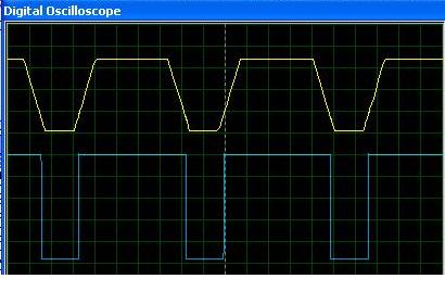
Could you please tell me if you know a way to take a signal like yellow one if I give a PWM like blue one. The magnitude blue signal is 3.3V and the yellow one is 5 V.
I want to make this to switch my DC - DC converter softly. I think the peaks at the output of DC DC Converter may be removed with this delayed PWM.
This can be done either with a 74HCT chip as i said or using two transistors like my previous post.
What is the output requirement of the 5v output signal?
If it is a few mA then it can work as it is.
Do you need the rising and falling edge of the 5v to be slow like your yellow signal?
I have to say that your traces are strange, i can see the yellow signal having a slow rising when the blue goes high
but how does the yellow start to fall before it gets the falling edge of the blue signal?
There is no problem to make 5 V output after your answer. I did it with 74HCT241. Now I want to add a rising and falling edge for 5 V like yellow signal. The duration is not too important. I will try if it decreases the output ripples or not.
{Do you need the rising and falling edge of the 5v to be slow like your yellow signal?}
So you need a slew rate limiter, ok but i have no idea how to do it,
an RC filter output will not have the result that you want, it will be curved and not trapezoid like your wave.
Alex
---------- Post added at 15:28 ---------- Previous post was at 15:19 ----------
The only circuit i have found is a Miller Integrator, but i don't have any ready solution. Miller Integrator
This site uses cookies to help personalise content, tailor your experience and to keep you logged in if you register.
By continuing to use this site, you are consenting to our use of cookies.