Continue to Site

Welcome to EDAboard.com

Welcome to our site! EDAboard.com is an international Electronics Discussion Forum focused on EDA software, circuits, schematics, books, theory, papers, asic, pld, 8051, DSP, Network, RF, Analog Design, PCB, Service Manuals... and a whole lot more! To participate you need to register. Registration is free. Click here to register now.

Constant Current source for thermistor

Status
Not open for further replies.

Neveth

Newbie level 6
Joined
Aug 17, 2009
Messages
11
Helped
0
Reputation
0
Reaction score
0
Trophy points
1,281
Location
Coimbatore, India
Activity points
1,372
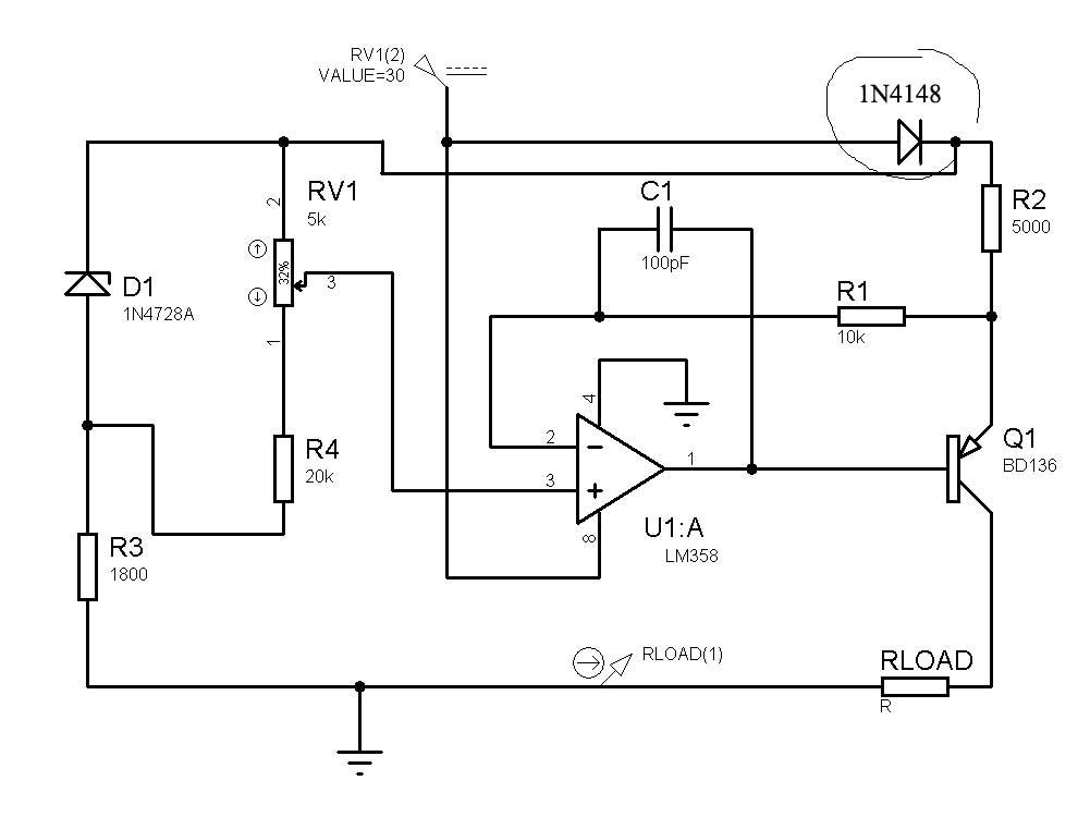
Guys, can anyone post me a circuit of constant current source for thermistor ?
But my range is high, its from 5 ohm to 200k ohm.
Actually i tried it with two floating current circuits, 1mA and .1mA ! Even though i succeed in it, i m having other kind of trouble. That makes me to look for grounded current circuit.

Can anyone help me in this thing ?

Thanks in advance
 

The change is over 4 decades, so thinking realistically you should consider a current source that has switchable range, say, every decade ..

IanP
:wink:
 

AD7793, AD7794 sigma-delta adc's has built-in 1mA and 0.1mA precision current sources
 
Last edited:

1mA current for a 200K resistor would require 200 volts !!!!!!8O

Alex
 

I have use a circuit like the one attached for 4-20ma constant current source , i have increased the emitter resistor from 100 ohm (intended for 100-1k loads and 4-20mA) to 5k for 100uA.
The divider in the positive input is from a 3v zener to give some input regulation, you can use a lower value.
The circuit compares the voltage set to the positive input with the voltage drop on the 5k resistor in the emitter,
5K*0.1ma=0.5v (so 0.5v in positive input will give 0.1mA in the output), you can increase it more if you want.
As you can see the current swing from 5 ohm to 200k is 2uA, maybe it will suit you.

current(y-axis)_vs_load_resistor(x-axis).jpg100uA_constant_current.jpg

Alex
 
Last edited:

Alexan_e scheme seems to be OK. I made 4-20mA (0-20mA) source and if you want it contact me.

draganm
 
5K*0.1ma=0.5v (so 0.5v in positive input will give 0.1mA in the output), you can increase it more if you want.

One small correction to my post,
the line above is correct for the same circuit connected to the low side and using a npn output transistor,
in the circuit i have provided the voltage at the negative input is Vcc-(voltage drop at the resistor of 5k) = 29.5v so you need 29.5v in the positive input to have 100uA output current.

Alex

---------- Post added at 16:20 ---------- Previous post was at 15:02 ----------

You also need an opamp that can give an output voltage close to the power supply and can work with 30v single power ,
LM358 has a Vcc-1,5v max output voltage and will not work,you need about 29v in the base of the transistor.
You can also use a couple of diodes so the resistor on the emitter gets a lower voltage that the opamp
and in that case the opamp will be able to drive the transistor correctly.
The simulation model of the opamp was able to give that voltage in the output (23v )but the datasheet says Vcc-1.5v which seems to be correct from a test i made.

Alex
 
Last edited:

If you want to use the LM358 opamp something like this with 1 or 2 diodes will work.

100ua2.jpg

Alex
 

To avoid introducing a temperature dependant error, you would want to correct the circuit like below. If the +ve input from the pot is within common mode range, the circuit will work without a diode, by the way.


P.S.: I preferably use darlingtons or FETs as current source output transistors, otherwise the error caused by the base current is possibly too high for a precision circuit.
 

To avoid introducing a temperature dependant error, you would want to correct the circuit like below.

Haven't thought of that.

If the +ve input from the pot is within common mode range, the circuit will work without a diode, by the way.

LM358 has an input common-mode voltage range of 0 to Vcc-1.5v.
So a assume you mean a resistor in the emitter about 3 (or 4) times bigger that would create a voltage drop of about 1.5v so that the positive input can be set to Vcc-1.5v.

I'm wondering are there any opamps that have an input common-mode range (top) of Vcc-0.5v for example and a max output of Vcc-2v.
If they exist then i think they wouldn't be able to drive the base with the voltage needed (in this circuit with 5k) but they would still be in the common mode range of the input.

P.S.: I preferably use darlingtons or FETs as current source output transistors, otherwise the error caused by the base current is possibly too high for a precision circuit.

I haven't thought of that either but this circuit was intended for higher current so i assume it didn't matter (4-20ma).
Would this be with a fet or a mosfet?
Can you please post a sample output stage with a fet/mosfet.

Alex
 
Last edited:

they wouldn't be able to drive the base with the voltage needed
It's true, that the circuit has also requirements for output voltage range. By using an IO rail-to-rail OP, you don't have to think about.
Can you please post a sample output stage with a fet/mosfet.
You can simply place a PMOS FET (regular enhancement mode) instead of the PNP BJT. Depletion mode FETs, e.g. P junction FETs won't be able to should down the current completely with the sense resistor referenced to the positive supply. For a fixed current source, they can work if the threshold voltage is sufficient low. Large FETs possibly create stability problems with fast OPs due to the gate capacitance, but the compensation can be adjusted for it.
 

I send you collection of articles-circuits for FET constant current. Have a good work.
 

Attachments

  • Current source-FET.rar
    1.4 MB · Views: 180

**broken link removed**

In fig.20 there is a constant current source (around op1 and TR1) pushing constant current through the KTY84.
 

Status
Not open for further replies.

Part and Inventory Search

Welcome to EDABoard.com

Sponsor

Back
Top