Continue to Site

Welcome to EDAboard.com

Welcome to our site! EDAboard.com is an international Electronics Discussion Forum focused on EDA software, circuits, schematics, books, theory, papers, asic, pld, 8051, DSP, Network, RF, Analog Design, PCB, Service Manuals... and a whole lot more! To participate you need to register. Registration is free. Click here to register now.

Can't find wanted pulse transformer. Build it myself ??

Status
Not open for further replies.

elec4fun

Full Member level 3
Joined
Jan 24, 2005
Messages
159
Helped
38
Reputation
76
Reaction score
31
Trophy points
1,308
Location
Nice, France
Activity points
897
Hello,

I have to design an transformer driven line interface.

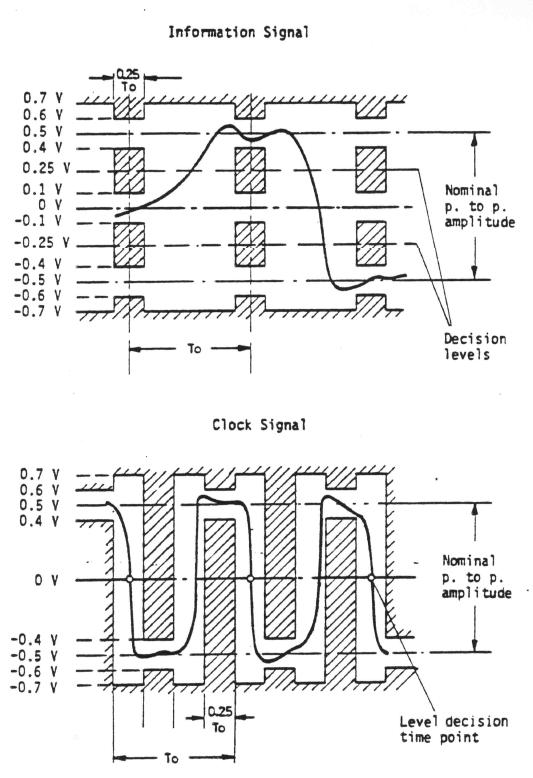
The standard is EUROCOM-D1 (an old military one). It uses:

- twisted pair
- AMI coding
- level 500mV/-500mV
- impedance 120 ohms
- speed from 128kbps to 1Mbps

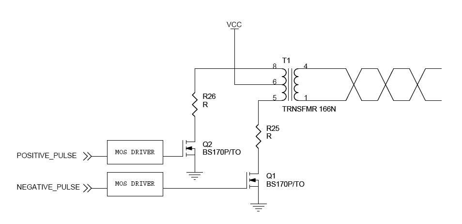
I couldn't find an integrated line driver chip. So I have to build it myself and choose th right transformer.

The closest standard I could find is T1/E1 but it doesn't work as low as 128kbps and levels and much higher...I had to find a transformer with a larger inductance value.

I found this MURATA POWER SOLUTIONS - 78602/1C, a 2mH 1:1:1 tranformer. This one could do the job but the transformer ratio is too low.

I'd like to have a voltage of about 3V on the primary side and the secondary must be 500mV. This gives me a ratio of 6:1 and I can't find such a transformer.

Do you think I could build such a transformer myself ? Have you ever experimented something like this ? Does someone have an idea for my line driver design ?

Thanks in advance.

Regards,
Franck.
 

I guess, with 1:1 ratio many available broadband transformers would do for your application, e.g. some ISDN or ADSL transformers.
But a specification of acceptable pulseshape distortion and amplitude drop would be needed to select it. 6:1 is rather uncomfortable
in terms of bandwidth, I fear.

I see, that Mini-Circuits has 1:36 ohms ratio (1:6 voltage) 0.03 - 20 MHz transformer T36-1. Of course, you
can make the transformer yourself, but the problems are basically the same as with retail types.
 

Thanks for the tips. I'll try to get a T31-1 transformer and I'll give it a try.

The reason why I don't want to use a 1:1 ratio is that I don't want to have to deal with a low voltage (500mV) on the primary side.

With such a low voltage, a 100mV overshoot or ringing due to the primary side MOSFET driver would be non negligible. On the other hand, if I had to deal with a primary voltage of about 3V, signal distortions and noise would be relatively smaller regarding the pulse amplitude.

What do you think about that ?

I'll post the acceptable signal shape today.

Thanks for your help.
 

I don't see, that parasitic effects are necessarily larger with lower driver voltage, because the load impedance is also considerably lower.
There are various driver techniques possible anyway.
 

This is the pulse shape needed:


Cable length is max 50m.

For the driver, I was thinking of something like this:


I guess, the driver should better have constant output impedance to absorb reflected signals travelling back the line? CMOS gates with resistive dividers would do for the required power level.
 

Thanks for your patience, I know I'm not goot at analog design at all :)

Anyway, in a ti document I found this:


I think it's what you are thinking about when you talk about constant output impedance...

Do you think something like this will be ok ? :


IN1 = 0, IN2 = 1 -> positive pulse
IN1 = 1, IN2 = 0 -> negative pulse
IN1 = 1, IN2 = 1 -> no pulse

I'll have to adjust R1, R2, R3, R4 to have 120ohms from the point of view of the line considering the transformer ratio.
 

The n and p FET gates have same polarity, not inverted.

My idea was to drive the resistor network from CMOS logic gates directly.
They can drive the < 10 mA needed even with a 1:1 transformer.
 

    elec4fun

    Points: 2
    Helpful Answer Positive Rating
The schematics was a kind of "block diagram" and yes, I'll use a cmos gate or something like an **broken link removed**.

I'll experiment during the next week and I'll keep you posted.

Thanks.
 

I wonder, why you are always considering driver solutions, that would be required for several 100 mA or even A? How about e.g. 74HC04?

0.5V/60 ohm = 8.3mA for a both sided terminated driver
 

I did some tests and everything seems to be alright. This is the waveform a got:

4µs pulse:


1us pulse:


Zoom on rising edge:


Is there any trick to minimize the winding capacitance/leakage inductor effect on the rising edge ?[/img]
 

It's a RLC circuit. L and C are mainly transformer parameters, R is defined by the transmission line impedance and termination resistors.
 

So what if I put a parallel capacitor (few pF) on the primary side ? Rising time would be impacted but oscillation should be less important...
 

Status
Not open for further replies.

Similar threads

Part and Inventory Search

Welcome to EDABoard.com

Sponsor

Back
Top