Continue to Site

Welcome to EDAboard.com

Welcome to our site! EDAboard.com is an international Electronics Discussion Forum focused on EDA software, circuits, schematics, books, theory, papers, asic, pld, 8051, DSP, Network, RF, Analog Design, PCB, Service Manuals... and a whole lot more! To participate you need to register. Registration is free. Click here to register now.

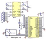
P89V51RD2 programmer Circuit

Status
Not open for further replies.
is this switch S in its correct position?? No need to add any other thing???

Moreover alongwith it unchecking the "Use DTR to control RST" in the advanced options of Flash Magic??

Plz reply soon
Thanx a lot for your cooperation
 

Attachments

  • RD2_ISP_Programmer3444.JPG
    RD2_ISP_Programmer3444.JPG
    70.3 KB · Views: 77

the position of switch is correct...
do the following.. press the reset switch.. ( dont release it).. Click the program button on flash magic.. it will ask reset the board, then release the reset switch.

or one more option

after it asks to reset the device power off and on it..
 
@ckshivaram: "thnx a ton!!"
one more thing, can i place an led at p2.0 with a resistor of 220 ohm to toggle as to get satisfaction that my m.c.u has been programmed
I am talking of putting the led on the programmer board itself which i have attached in my last post.

And see in the same image that a 100nf capacitor has been provided at the vcc pin of the 40 pin \mu c ...is it provided for filtering the noise?
 

ok i willfirst burn the program of checking a toggle of led on p2.0 . then will take out the uc from the porgrammer and will use a separate circuit for the checking of a led status.
bt u did'nt answered my second question
thanx a lot.
 

soory ,,, i missed the seccond part......

Its a very good practise to keep a low value at power input to any device.. it not only blocks noise but,

it regulates chunk current.. some times some devices use 10uf along with 100nF.. it blocks bulk current and chunk current to the device
 
are the capacitors 100nf and 1uf are both of ceramic type
if any one is electrolytic or ceramic then do let me know..
if any electrolytic plz indicate in th diagram in my earlier post(the positive and the negative signs)...
plz cooperate
thanx
 

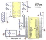
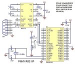
No guyz! I am not getting my device programmed.. The reset device window appears but even when the reset switch is released or even when it is pressed, nothing happens(window doesn't disappear)...here are some images showing what voltage is appearing on the board..(images attached) ....the signal ground of serial port connected with the ground of the programmer..even tried of placing a wire on the reset pin shorting the pin9(reset pin of the uc) with the vcc for 2 seconds and even more..But the window doesn't disappear..:(
Plz help i have to construct the project within limited time...
thanxx(see the images too..)
 

Attachments

  • INITIAL_STAGERD2_ISP_ProgrammerINITIAL.JPG
    INITIAL_STAGERD2_ISP_ProgrammerINITIAL.JPG
    74.8 KB · Views: 73
  • FINAL_STAGERD2_ISP_Programmer.JPG
    FINAL_STAGERD2_ISP_Programmer.JPG
    77.8 KB · Views: 72

moreover, i have unchecked the "use DTR to control RST" and in timeouts "Use my timeouts for ISP operations" and in misc i have unchecked "Play wave file when programming complete" and all the other options in the misc have been unchecked..moreover in communications i have unchecked "Half duplex communications" ...Am i doing anything wrong plz let me know...
 

Status
Not open for further replies.

Part and Inventory Search

Welcome to EDABoard.com

Sponsor

Back
Top