Welcome to our site! EDAboard.com is an international Electronics Discussion Forum focused on EDA software, circuits, schematics, books, theory, papers, asic, pld, 8051, DSP, Network, RF, Analog Design, PCB, Service Manuals... and a whole lot more! To participate you need to register. Registration is free. Click here to register now.
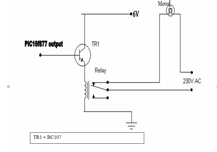
1. To turn the relay on, the base of the transistor has to be lifted to a voltage equal to the relay coil voltage added to Vbe of the transistor. The PIC can only produce a maximum output voltage of 5V so the relay coil would have to be rated no higher than 4.4V.
2. For a relay with contacts rated to run a mains motor, the coil would have a low resistance and neither the BC107 or the PIC would could produce enough drive current.
3. If the relay did manage to operate, as it switched off, the collapsing magnetic field in its coil would produce a voltage that would destroy the BC107 and probably the PIC as well.
Solution:
1. Use a transistor rated at higher collector current. A darlighton type would be netter than a signle junction transistor.
2. the transistor switches on when a current flows between its base and emitter pins so ground the emitter and put the relay coil in the collect instead. The same relay current will flow as in your circuit but the base voltage only has to be raised a small amount for it to operate.
3. Add a resistor in series with the base pin. The Base to emitter junction of a transistor tries to hold a constant voltage which might overload the PIC output. As the base current only needs to be relatively low you can add a resistor to limit the current and protect the PIC.
4. Connect a diode across the relay coil so it is NOT normally conducting, in other words with the cathode to the supply and anode to the collector. When the relay is turned off and the field collapses it produces a voltage in the opposite polarity to that applied so the diode will conduct it safely away and protect the transistor.
Be careful ! Mains voltages can be lethal. Make sure the AC and DC sides of the circuit are isolated and that the relay is rated to switch an inductive load.
BC517 should be OK, it depends on the relay coil current.
If you have a data sheet for the relay it should tell you it's coil voltage and current. You should aim for the correct voltage and make sure the transistor can continuously carry the current with a 50% safety margin. For example, if the coil is 100mA the transistor should be rated no less than 150mA. If the coil current is not specified you can calculate it by measuring the resistance with a test meter and dividing it into the voltage. For example a 5V coil (which appears to be what you are using) measuring 20Ω would draw a current of 5/20 Amps or 250mA.
The value of the resistor in the base pin can be calculated by dividing the voltage it drops by the base current. The base current is the coil current divided by the transistor's gain. For example, if the coil draws 250mA and the transistors gain is 100, the base current would be 2.5mA. The resistor has to drop the PIC output voltage down to Vbe of the transistor which is probably 5V down to 0.6V at 2.5mA so the value would be 4.4/0.0025 or 1760Ω. In Practice use a lower value, I would suggest 1200Ω (1.2KΩ) to ensure the transistor was fully driven.
The diode across the coil only carries a very brief pulse of current at the moment the relay switches off, I would suggest a 1N4001 or similar type.
The first test would be, if the minimal pull-in voltage of about 4.5 V is actually achieved across the
relays coil. Otherwise, something is wrong with your circuit, not the relays. You don't need to
connect a load for the test.
This site uses cookies to help personalise content, tailor your experience and to keep you logged in if you register.
By continuing to use this site, you are consenting to our use of cookies.