Mapuia
Junior Member level 3

I'm having a problem with what I thought would be a simple minor project: A noise filter for a phone-ADSL combo line.
For some 15 years, I've been using separate landlines for voice calls and for ADSL+ internet. This is because I use a landline phone more than I do mobiles and I don't like the hiss on combo lines. It belatedly dawned on me that the noise must be caused by inadequate filtering at the phone/modem splitter. Sure enough, the one I have has just a single 1mH inductor and one 39nF capacitor, and those that I can find in the local market are no better.
So I thought I'd make a more effective micro-filter and, considering the wide separation between the <4kHz bandwidth for voice and >25kHz for ADSL signals, I expected it to be a breeze. I was wrong.
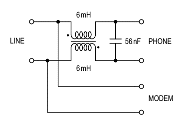
I thought I'd start with a simple one-stage LC filter to see what effect I get. As I don't stock inductors in the range I wanted, I wound one on a small ferrite toroid salvaged from a broken device. I made two 6mH windings, bifilar-wound on the same core, connected them anti-phase, one on each side of the phone line with a capacitor at the output side. Like this -

Well, the result is that the modem gets disconnected whenever I take the phone handset off-hook. I changed the phase of one inductor, tried various capacitor values, placed series resistors after the capacitor, removed one inductor to make an unbalanced LC filter. Nothing works.
I know there are more complex filters but I've also seen schematics of cheap commercial filters with configurations similar to mine. What am I doing wrong?
For some 15 years, I've been using separate landlines for voice calls and for ADSL+ internet. This is because I use a landline phone more than I do mobiles and I don't like the hiss on combo lines. It belatedly dawned on me that the noise must be caused by inadequate filtering at the phone/modem splitter. Sure enough, the one I have has just a single 1mH inductor and one 39nF capacitor, and those that I can find in the local market are no better.
So I thought I'd make a more effective micro-filter and, considering the wide separation between the <4kHz bandwidth for voice and >25kHz for ADSL signals, I expected it to be a breeze. I was wrong.
I thought I'd start with a simple one-stage LC filter to see what effect I get. As I don't stock inductors in the range I wanted, I wound one on a small ferrite toroid salvaged from a broken device. I made two 6mH windings, bifilar-wound on the same core, connected them anti-phase, one on each side of the phone line with a capacitor at the output side. Like this -

Well, the result is that the modem gets disconnected whenever I take the phone handset off-hook. I changed the phase of one inductor, tried various capacitor values, placed series resistors after the capacitor, removed one inductor to make an unbalanced LC filter. Nothing works.
I know there are more complex filters but I've also seen schematics of cheap commercial filters with configurations similar to mine. What am I doing wrong?


