Continue to Site

Welcome to EDAboard.com

Welcome to our site! EDAboard.com is an international Electronics Discussion Forum focused on EDA software, circuits, schematics, books, theory, papers, asic, pld, 8051, DSP, Network, RF, Analog Design, PCB, Service Manuals... and a whole lot more! To participate you need to register. Registration is free. Click here to register now.

Hitting me with serial port

Status
Not open for further replies.

pieldetoro

Newbie level 5
Joined
Nov 7, 2011
Messages
9
Helped
0
Reputation
0
Reaction score
0
Trophy points
1,281
Activity points
1,348
Hi guys,

I've wasted many days with a problem with the serial port.

I'm using Mega2560, MAX232 (DB9) and WAVECOM Fastrack GSM modem (DB15).

- My MAX232 connects fine with PC-RS232. I open two TeraTerm windows (one connected to Arduino, another one to PC serial port) and no problems sending and receiving.

- No problems connecting PC to modem with original cable (DB9 to DB15).

- I have an old 56K modem. I tried the MAX232 and runs smoothly.

But ... I can't connect the MAX232 to the GSM modem.

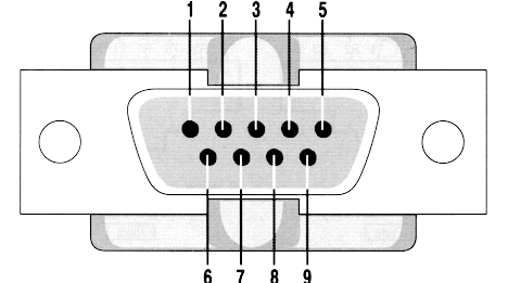
- To connect MAX232 to GSM-modem I used a three-wire cable RX (2/6), TX (3/2) and GND (5/9). Where (X = DB9/Y = DB15).

- I found a clue. I could connect from PC to modem using 4 wires. The fourth wire going from RTS (DB9 pin 7) to CTS (DB15 pin 11).

- I discovered I can disable flow control on modem. The command is AT+IFC=0,0. It did not work.

- I've also tried to tie CTS and RTS signals on modem. It did not work.

- By the way, also tied DCD, DTR and DTS.

wires.jpg

But still no response.

How I can have the "fourth wire" (CTS to RTS) from MAX232?

Any ideas? THX!
 

I will recommand you to see the connection of GSM modem first.....I think GSM modem need only RX TX and GND

refer the link.....
http://www.atmel.com/dyn/resources/prod_documents/doc8016.pdf

At least with the best of my knowledge MAX232 has only RX TX pair combination ....It dose not implement the Hardware Flow control....

with regards,

Milind
 
Thanks Milind. I already tried connecting only 3 wires. Works fine with all (PIC <-> PC, PIC <-> OLD MODEM 56K) but does not work with modem WAVECOM.
There must be something different in this modem.
I think the side of the modem must have a flow control requirement. I tried to disable flow control with an AT command (AT+IFC=0,0), but still the same.
I've also read that I should tie RTS and CTS at modem side, but neither works.
 

With all GSM modems I was yet aware of, it has been sufficient to tie modem RTS (TTL level) to ground and use RxD and TxD only. Buffer capacities have to be considered of course. Also the receiving application must provide some RxD buffering.
 
More FAQ's just for your info ---

GSM FAQ

Tanks Milind.
I found this. I had already tried, but I will try again.

Q. What flow control does the GSM module expect on the 9 way D type RS232 interface?

A. Consequently, it is recommended that you explicitly specify flow control as part of the initialisation process. AT+IFC=0,0 will turn flow control off, AT+IFC=2,2 will turn hardware flow control on. This command is described in V25ter, paragraph 6.2.12.
 

Hi pieldetoro,

Flow control means complete Serial functionality.....There is a protocol to be followed in case you are doing UART communcation ... Like one need to CTS( Clear to send ) or RTS means "Request To Send" will get controlled with the help of pin status ....thus one uses flow control need to think and implement the complete protocol for the Hardware ...
Refer -
Text-Terminal-HOWTO: Flow Control (Handshaking)
RS-232 - Wikipedia, the free encyclopedia
**broken link removed**

May be helpful you to understand....

with regards,

Milind
 
You mean this interfacing?
I was talking about TTL levels. In case of RS232 levels, RTS has to be connected to a positive voltage. The said jumper to CTS should normally provide it, but I'm not sure about the exact behaviour of the said modem. I must confess, that I'm surprized about the non-standard "RS-232" interface of the device. Can you provide a full documentation?

thus one uses flow control need to think and implement the complete protocol for the Hardware
I guess, you didn't completely understand the purpose of flow control. It's required to avoid overflow of the respective receiver buffers. As long as buffers are large enough respectively the data amount is limited, there won't be a problem and you you can permanently enable the transmitters. This has been possible with any GSM modem I've been yet working with, including Wavecom, but not the said device.
 
Can you provide a full documentation?

It seems that it is a standard RS-232:
Serial interface RS232 V.24/V.28 Autobauding function
AT command set based on V.25ter and GSM 07.05 & 07.07
Complete specs

It should work with only three wires. The only question is whether it requires more pins that RX, TX, and GND.
In any case, should be enough to tie CTS and RTS. Right?
 

The documentation isn't very clear about the exact function of the handshake signal. It seems to suggest, that the RS232 interface is rather confugured to fixed 115k than baud autodetect. But you should be able to determine supported baud rates and which signals are required, starting from the working PC communication, disconnecting and connecting individual wires. It may be the case, that the software (AT) manual of the modem has additional information.
 
The documentation isn't very clear about the exact function of the handshake signal. It seems to suggest, that the RS232 interface is rather confugured to fixed 115k than baud autodetect. But you should be able to determine supported baud rates and which signals are required, starting from the working PC communication, disconnecting and connecting individual wires. It may be the case, that the software (AT) manual of the modem has additional information.

Yes, by AT+IPR=<speed> I can select the baudrate. I'll try various speeds and disconnect cables one by one, as you indicate.

Thank you very much.
 

According to page 12 of the datasheet of your device pin 2 of the 15pin connector is Tx and you have connected it to the DB9 Tx and pin6 is Rx and you have also connected it to the Rx of DB9.
From what I can tell you haven't crossed the Tx and Rx connections (Tx -> Rx and Rx -> Tx)

Alex
 

According to page 12 of the datasheet of your device pin 2 of the 15pin connector is Tx and you have connected it to the DB9 Tx and pin6 is Rx and you have also connected it to the Rx of DB9.
From what I can tell you haven't crossed the Tx and Rx connections (Tx -> Rx and Rx -> Tx)

Yes, that I can confirm this. I successfully test PC with modem connection using 4 wires:
DB9 - DB15
2 ---- 6 (TX-RX)
3 ---- 2 (RX-TX)
5 ---- 9 (GND-GND)
and
7 --- 11 (RTS-CTS)

But I can not use this last wire with MAX232.
 

DB9 - DB15
2 ---- 6 (TX-RX)
3 ---- 2 (RX-TX)

Pin2 of DB9 is Rx and pin6 of DB15 is also Rx so what you have is Rx-Rx and not TX-RX
It is the same with Tx, Pin3 of DB9 is Tx and pin2 of DB15 is also Tx so you have Tx-Tx

You haven't crossed the wires, what you need is

DB9 - DB15
3 ---- 6 (TX-RX)
2 ---- 2 (RX-TX)

Alex

---------- Post added at 16:57 ---------- Previous post was at 16:53 ----------

You are using the standard DB9 pinout right?

9-pinout.gif
 
You haven't crossed the wires, what you need is

DB9 - DB15
3 ---- 6 (TX-RX)
2 ---- 2 (RX-TX)

It's true. You're right.
I can't believe, is a huge mistake!!!

As soon as I get home will check the wires. I hope this is the solution.

Thank you very very very much Alex.
 

I can't believe, is a huge mistake!!!

:-( Yes, but my mistake was when I wrote the post.

Upon arriving home I checked the wires. They are OK.

The connections are:
DB9 - DB15
3 ---- 6 (TX-RX)
2 ---- 2 (RX-TX)
5 ---- 9 (GND-GND)

The same problem. Still does not connect to the modem.

If tie CTS to RTS does not work.

If I turn flow control to none (using AT+IFC=0,0) does not work.

But... If I connect pin 12 (RTS) to GND and pin 11 (CTS) to +5V... Surprisingly, the modem answers! :lol:

Will there be any problem with the circuit if applied +5V to CTS? Is it safe?
 

If I connect pin 12 (RTS) to GND and pin 11 (CTS) to +5V... Surprisingly, the modem answers!
According to the manual you provided, CTS is an output and RTS an input. So connecting CTS anyhow shouldn't affect the modem operation. Connecting RTS to GND is equivalent to open circuit with standard RS232 drivers, an undefined value according to RS232 specification but typically identical to negative level. I would rather expect +5V (a valid positive level) at RTS to enable the modem. Either the modem is operating different from expectable standards, or your observations got mixed up somehow.
 

Status
Not open for further replies.

Part and Inventory Search

Welcome to EDABoard.com

Sponsor

Back
Top