Continue to Site

Welcome to EDAboard.com

Welcome to our site! EDAboard.com is an international Electronics Discussion Forum focused on EDA software, circuits, schematics, books, theory, papers, asic, pld, 8051, DSP, Network, RF, Analog Design, PCB, Service Manuals... and a whole lot more! To participate you need to register. Registration is free. Click here to register now.

Inverter (built in battery charger) as UPS

Status
Not open for further replies.

sam781

Full Member level 4
Joined
Oct 22, 2011
Messages
212
Helped
7
Reputation
14
Reaction score
7
Trophy points
1,298
Activity points
2,757
I've bought an 500W Inverter cum charger. It has terminal -
1. Charger Input -AC power in (230V)
2. Inverter Output -AC power Out (230V)
3. 12V DC Battery connection

It's operating principle is as below -
When AC power is available in the charger input terminal the battery is getting charged and there is no power output at the inverter output terminal.
When AC power is unavailable (commercial power failure) there is no power in charger input terminal and output AC power becomes avialble at the inverter output terminal.

So, by connecting electrical loads in inverter output terminal I can get it work at the time of power failure. But I want make this as a UPS. How can I make it?
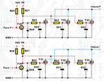
 

Circuit2.jpgCircuit3.jpgCircuit.jpg
 

first you have to understand the UPS operation modes and finally you have to hack/modify your inverter. the UPS operation modes are 1)OFF-Line 2) ON-Line 3) Line-Interactive.
OFF-Line is similar to your inverter, IN online mode both raw power and battrey will feed the DC bus and inverter is always ON and powered with DC bus. IN case of power failure still DC bus is alive due to battery and inverter is on. we cannot observe any interference or fluctuation. YOu have to open your inverter and let us know the components
 

hello tpeter,
what's the language of urs attached cct. diagram,how to translate it into english.
thanks. ch wazir

Its on Serbian language written on latinic (we also writing on our native cyrilic).

Faza = Phase
Mreža = AC Line
Pretvarač = Inverter
Punjenje = Charging
Srednja sekundara = Middle of trafo secundar
Izlazni = Out
Srednji = Middle
Mrežni napon = AC Line


On this address You wil find complete project 12V to 220V Inverter :
Pretvarac 12 V Dc na 220 AC
 
Last edited:
I want to make offline UPS by connecting a changeover. Can I connect only the phase with the changeover keeping neutral connected each other?

If yes. Which wire of inverter output should be connected with the power line's neutral?
 
Last edited:
I want to make offline UPS by connecting a changeover. Can I connect only the phase with the changeover keeping neutral connected each other?

If yes. Which wire of inverter output should be connected with the power line's neutral?
Yes you can select any wire from output socket as a common neutral.
But remember during backup mode(inverter),you can not touch battery terminals,if your inverter is smps.
Because in smps(high frequency transformer,chopper) inverters,negative of 12v dc and negative of 260v dc is almost common(connected with each other).

---------- Post added at 10:48 ---------- Previous post was at 10:30 ----------

****************************************************************

'* Naziv : OSCILATOR.BAS *

'* Autor : Milanovic V. *

'* Napomena : Primer softverskog oscilovanja *

'* Datum : 16.01.2006 *

'* Verzija : 1.0 *

'****************************************************************


Pocetak:


Low PortB.5 ' Pin B.5 postavi na 0

High PortB.4 ' Pin B.4 postavi na 1

pause 10


Low PortB.4 ' Pin B.4 postavi na 0

High PortB.5 ' Pin B.5 postavi na 1

pause 10


Goto Pocetak


End ' Kraj program

---------------------------------------------------------------------------------
Hi,tpetar.
Above paragraphs are complete source code for inverter with pic16F677.
 

Many times one wire is already directly attaced to neutral of socket. This can be checked with a multimeter.In sme ups system it is connected when internal relay operates.
 

Thanks all of you for your variable inputs.
 

At low **broken link removed**, my ups does this sort of thing fine. Once you start make them do significant amounts of power for extended time, mine gets the transformer smells, not hurt, but unhappliy hot. I assume that this is because they assume 20 min run time at higher wattage, and then it's battery will be flat, so not long enough to get dangerously hot.
 

At low **broken link removed**, my ups does this sort of thing fine. Once you start make them do significant amounts of power for extended time, mine gets the transformer smells, not hurt, but unhappliy hot. I assume that this is because they assume 20 min run time at higher wattage, and then it's battery will be flat, so not long enough to get dangerously hot.
plz check your load that should be near about 70% of the total capacity,if the load is ok then check the driver of the switching amplifier.if all okay then the problem lies in output transformer which is made with the low quality core mareial.
i think it'll be helpful.regards
 

Status
Not open for further replies.

Similar threads

Part and Inventory Search

Welcome to EDABoard.com

Sponsor

Back
Top