Continue to Site

Welcome to EDAboard.com

Welcome to our site! EDAboard.com is an international Electronics Discussion Forum focused on EDA software, circuits, schematics, books, theory, papers, asic, pld, 8051, DSP, Network, RF, Analog Design, PCB, Service Manuals... and a whole lot more! To participate you need to register. Registration is free. Click here to register now.

feedback method in multiple output power supply

Status
Not open for further replies.

electrophysics

Member level 3
Joined
May 10, 2010
Messages
58
Helped
4
Reputation
8
Reaction score
4
Trophy points
1,288
Activity points
1,773
Hi,
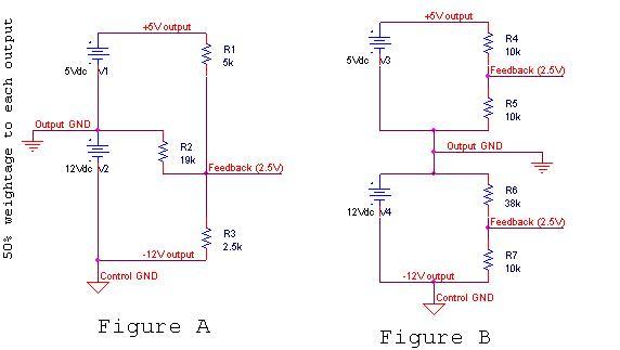
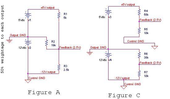
if we are designing a power supply having both positive as well as negative outputs w.r.t output ground. what technique is used to sense outputs if we want to take feedback from all negative and positive voltages at outputs in this multiple output power supply.
 

I think you need to explain your question. It's not clear what exactly you are looking for? If your control circuit ground and output ground are common, you can use simple resistive divider?
 

treat the most neg output as ground....do multiple weighted feedback from the rails ..referenced to that.
 

I was little surprised from these answers. so thought to first check it. I simulated it on PSpice and found it to be wrong to consider highest negative (in magnitude) as control ground and then take feedback from other outputs in weighted voltage resistors. the simulation gave me bad results.
 
.......i am wondering if, you have chosen the correct amount of turns for each output?

What topology are you using?

Are all the outputs loaded?

Is any output unloaded.

Are the loads on each output vastly different from each other.

......."PSpice"....is this a switch mode version of pspice........?

-only certain special types of simulator work for smps....eg LTSpice and simetrix etc.

Do each output on its own with 100%...does it reg that output correctly?

You made the current in the bottom feedback divider resistor was 100%....then % of current depending on accuracy required for the other top divider resistors?

What is the duty cycle?
 

time to post a schematic so we can see the problem.

Also a centre tapped winding with a bridge rectifier on the outside wires gives a pretty good result if the total voltage is regulated.
 
Last edited:

multiple outputs are never the blissfully accurate , wonderful things that they are made out to be.

....And when they do get it right, the current flow is often peaky and high in terms of its rms...............just look at the bias winding in a flyback.............you always need a series resistor there, to act as a filter with the output cap, because there are often big shards of current stabbing into that output cap, so you need the resistor.

very often , the main regulated winding goes into no-load......the controller then commands v low duty...and the current flow into the less regulated windings is very peaky...because it has only a tiny duty cycle gap to squeeze out of.

very often, the cost of auxiliary winding, aux winding output diodes, + aux winding filter costs more than just doing a separate smps off the main regulated winding.
 

Attached is the schematic. Fig A represents the your proposed method that I have perceived in simulation. while simulation of Fig A proved it to be wrong. suppose +5V is constant and accurate then in Fig A if -12V output has been changed to -13V then it will also disturb +5V feedback w.r.t control ground. now our control circuitry is connected to all resistors w.r.t control ground and will give wrong results. Also see Fig B for other results w.r.t each output.


---------- Post added at 08:02 ---------- Previous post was at 07:06 ----------

now replace Fig B with Fig C in the following attachment while Fig A remain the same. we can clearly see that with variation in -12V output to -13V will change +5V feedback level.


Last edited:

Of course it's impossible for one control loop to independently control two output voltages. Forcing a change on one will force a change on the other. Having weighted feedback allows you to have mediocre regulation on both outputs, rather than good regulation on one output and poor regulation on the others. But it can't eliminate cross regulation issues entirely. That's because there is only one power converter which cannot change the behavior of one output without affecting the other. You can improve cross regulation with novel circuit design (optimal transformers, coupled inductors, etc), but that will always be a limitation. To truly get independent regulation you need independent controllers and feedback loops somewhere.

Also I'm not exactly sure but I think your simulations are to simplified to really predict what your cross regulation will be. It's usually governed by transformer properties and output filters, and just doing a test with DC sources may give you deceptive results.
 

Status
Not open for further replies.

Similar threads

Part and Inventory Search

Welcome to EDABoard.com

Sponsor

Back
Top