Continue to Site

Welcome to EDAboard.com

Welcome to our site! EDAboard.com is an international Electronics Discussion Forum focused on EDA software, circuits, schematics, books, theory, papers, asic, pld, 8051, DSP, Network, RF, Analog Design, PCB, Service Manuals... and a whole lot more! To participate you need to register. Registration is free. Click here to register now.

IR Jammer Circuit not working

Status
Not open for further replies.
Hey I found one would this work with my circuit?

circuit-astable-555.jpg
 

By using 74HC08, output of two 555 is connected to the two inputs, output of the gate is connected to the base resistor ...
 

Thank you but is there a alternative to that gate? Cannot seem to find that one at the stores in my area. Also how does this work i don't get how by merging the two signals it works? Does it amplify them? or what?

Thank you for all your help!
 

Just connect the output of above circuit to the pin number 4 of your first circuit..(before that disconnect the pin number 4 of first circuit from vcc)

Then adjust the frequency of above circuit to about 1khz...
 

Would i just use a resistor to adjust to 1khz? if so what ohm? thanks
 

I think you have to start with the basics. Try this book :

50 - 555 Circuits

Somewhere inside there should be a schematic of two 555 controlling each other, maybe a multi tone siren ;) Then you can skip the gate :)
 

Thank you but what is T1 and T2 or should i not worry about those?
 

or use this one
Astable 555 Square Wave Calculator

---------- Post added at 20:51 ---------- Previous post was at 20:47 ----------

or
555 Astable Circuit Calculator

---------- Post added at 20:54 ---------- Previous post was at 20:51 ----------

use
C1=0.01 uF
R1 = 10K
R2 = 68K
----------------
frequency = 1KHz aprox
 
Perfect thanks will go pick up the materials and tell you guys the outcome!
 

I Have been looking at this diagram and was wondering if 7 should be connected to something i have a 10 uf capacitor connected to pin 5 but am not sure where 7 goes?

TV-RemoteJammer.gif
 

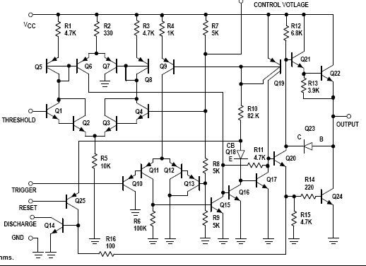
Ya im not very sure about all of the programming to my mind the 555 seems like the easiest for my does anybody have a schematic of this 555 MV working

Thanks all!

Here is a 555-based oscillator that may do what you want. All capacitors are in uF, unless noted. I used polystyrene for my timing components. You can use regular ceramic or mylar (polyester). IC1B modulates IC1A. The carrier was 38Kz. I used an LM556, which is just 2 LM555's in a single package. You can use the pin names to redraw it using two 555's.


John

Edit: Wow, over 10 posts in the time it took me to type and up load that. Sorry for the duplication.
 
John,

this is what I meant - one 555 is controlling the other ( just did not had the schematic in hand ), no need to use the logic gate, just need to add a transistor and more LEDs ;)
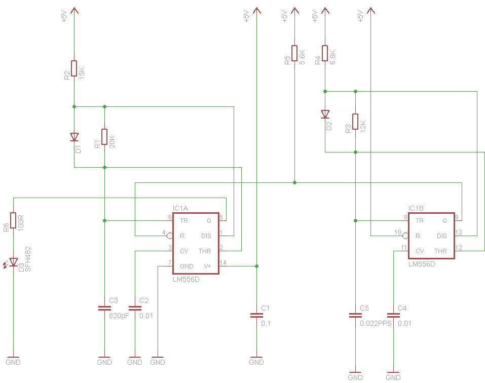
, probably to adjust R6 for good biasing of the switch transistor - if the transistor is BC337, it can carry 10 LEDs without a problem, base resistor about 1k :)

Hope this will close the article :) .
 

well it's not working again here's what i got:

My original circuit instead of a 555 a 556 is in its place
The 556 is used for the following along with the original circuit.
MULTIVIBRATOR

R1 -10 ohm resistor
R2 -68 ohm resistor
C1 -0.01 uf capacitor

When I turn the circuit on the 556 gets 95F degrees (Very hot). and there are no kHZ getting to the led. Does anybody know why this is happening?

circuit-astable-555.jpg
 
Last edited:

There is something wrong ... it should not get hot. Check all connections again. Try to make the circuit as proposed by jpanhalt and add the final stage - more leds and switching transistor as I wrote previously.

---------- Post added at 10:36 ---------- Previous post was at 10:26 ----------

check power supply, this is usually where you have to start ... then look at the outputs - pin 3

It does not get hot until i connect 5 to 10 (output to reset) on the 556. Any ideas?
 

It does not get hot until i connect 5 to 10 (output to reset) on the 556. Any ideas?

That doesn't make sense. Pin 5 is output from one 555 section (IC1A). Connecting that directly to your power supply would not be good. True, 555's can source or sink, but that would create almost a dead short to ground.

Here is the schematic of a 555 so you can see what I mean. Q22 and Q24 are the output transistors.


Are you absolutely sure you connected pin 5 directly to V+ supply? Do you have the reset (pin 10) connected to the supply?

John
 
Status
Not open for further replies.

Similar threads

Part and Inventory Search

Welcome to EDABoard.com

Sponsor

Back
Top