Continue to Site

Welcome to EDAboard.com

Welcome to our site! EDAboard.com is an international Electronics Discussion Forum focused on EDA software, circuits, schematics, books, theory, papers, asic, pld, 8051, DSP, Network, RF, Analog Design, PCB, Service Manuals... and a whole lot more! To participate you need to register. Registration is free. Click here to register now.

Battery backup circuit

Status
Not open for further replies.

holabr

Member level 2
Joined
Feb 12, 2010
Messages
46
Helped
1
Reputation
2
Reaction score
1
Trophy points
1,288
Location
USA
Activity points
1,719
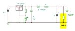
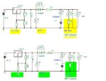
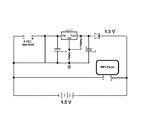
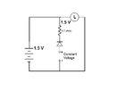
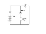
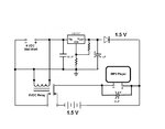
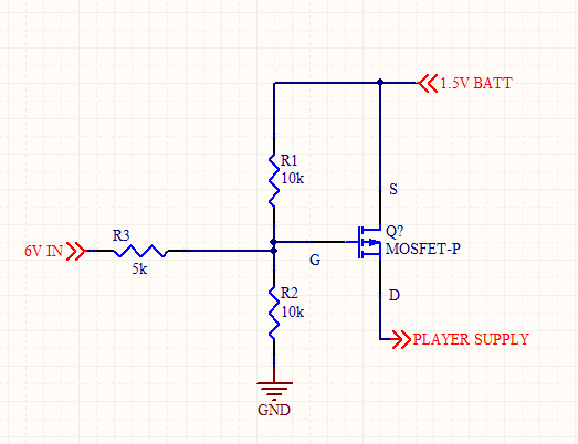
I'm planning to use an old MP3 player to provide music on hold for a small office PBX. Since the player must be restarted if it loses power, I would like to have a simple battery backup. If I use the circuit shown and the house power is maintained and provides sufficient amperage for the player will the battery remain charged? Is there any chance of causing the battery to overheat and/or explode? I am planning to use a standard 1.5 volt alkaline battery.
 

Attachments

  • Circuit.jpg
    Circuit.jpg
    26.4 KB · Views: 96

Basically it’s OK if this circuit allows for precise voltage adjustment in order to obtain 1.5V on the battery. Better try to use a small series resistor on the power circuit to have more room in adjusting the correct voltage.
 
I'm not sure I understand the "small series resistor". Where would it be placed in the circuit and what value would I need?
 

A small value let’ s say 2.2-4.7 ohms acting as current limiting resistor in series with the diode. The correct value are based on the current consumption in the circuit, and the external power supply we use.
 
efficiet way would be to use two Schottky diode (or a diode with a small forward voltage drop). One could be at same place as your diode and another in series with battery.
 

Why to use two diodes? Better to apply the external voltage to the battery (need to be adjusted in the limits of 1.5-1.55V), to obtain a similar situation of charging at tens of milliamps.
 
Reason is, if we will use one diode, we need to consider the worst case voltage differrence between bettery and supply. Say it is coming to be 0.5V. So in single diode topology, diode should drop at least this much voltage to make sure there there is no circulating current in circuit. more diode drop more energy loss.
Now if we could place two diode, we no longer depend on forward voltage of diodes and can choose as low as possible. This scheme will never allow to flow a circulation current irrespective of voltage differrence.
 

If I understand you correctly, these two circuits are what you are proposing.

In Circuit1, the variable regulator has to be adjusted to compensate for the diode and resistor to have 1.5 volts into the player. Also, if the battery drops below 1.5 volts, would this circuit bring the battery back up to charge?

In Circuit2, I would have less than 1.5 volts from the battery and the battery would never be charged. Is that right? I don't understand what problem Circuit2 is trying to overcome.

Do I need a particular type of diode or will anything I have in my parts box work as long as the output voltage to the player is sufficient?
 

Attachments

  • Circuit1.jpg
    Circuit1.jpg
    28.3 KB · Views: 83
  • Circuit2.jpg
    Circuit2.jpg
    26.9 KB · Views: 78

Ohh...
I did not observe that you want battery to be charged also. The second scheme will allow you to use a very low forward voltage drop diode without using a series resistor but will not allow any charging.
The first scheme will allow to charge the battery, but you have to be carefull in choosing the diode and feedback resistor. What could be your alkaline battery minimum voltage go? What is your current requirment for the player? You need to calculate the supply current from source based on mininmum battery current (player supply current + charging supply current) and define your supply current accordingly.
I am not sure if you could charge the Alkaline batterries like this, and hope you already would have studied about it.
 

This is the circuit I came up with using a relay to isolate the battery when the MP3 player is running off the AC wall wort. The problem is that the instant the power drops out and the relay switches to the battery, there is just enough of a delay that the player shuts off. Also when power is restored the player again shuts off when switching from battery to the AC. I tried adding the capacitor to hold enough charge to keep the player powered up until the relay switches but this doesn't seem to work. Any other ideas?
 

Attachments

  • Circuit1.jpg
    Circuit1.jpg
    55 KB · Views: 81

Instead of using relay you can try using a P-channel FET with gate threshold of less than 0.5V. You can connect the source of battery via 10k resistor and gate with 1.5V regulator output. Drain will go to player supply. Inherent diode in FET will help you to charge the battery at lower voltage (may be 1.3 - 1.4V, instead of 1.5V). I think FET will be fast enough to let the plater alive while switching the power.

---------- Post added at 07:12 ---------- Previous post was at 06:51 ----------

Instead of using relay you can try using a P-channel FET with gate threshold of less than 0.5V. You can connect the source of battery via 10k resistor and gate with 1.5V regulator output. Drain will go to player supply. Inherent diode in FET will help you to charge the battery at lower voltage (may be 1.3 - 1.4V, instead of 1.5V). I think FET will be fast enough to let the plater alive while switching the power.

I realized that gate will be left floating if source voltage will not present, and will cause FET to be off..
You can choose some FET like SI1307EDL, and connect it as figure attached.


ok. .
You can use transistor for switching pupose instead using relay. . bc 547, bc 548 etc all will do !!! Moreover there will be no delay!!!

Good Luck :)
 

Use a simple way, need only to adjust the voltage to compensate for the current consumption of the MP3 player…


See some example for 68mA and 125mA. Better to adjust voltage on the 317 output to obtain a 10-25mA current thru 1.5V battery.
 

Attachments

  • Charger 1.5V.JPG
    Charger 1.5V.JPG
    21.9 KB · Views: 86
  • test Charger 1.5V.JPG
    test Charger 1.5V.JPG
    71.2 KB · Views: 83
Last edited:
mister_rf

Is this what you are suggesting? I have the LM317 adjusted so I get exactly 1.5 volts accross the MP3 player when the battery is not in the circuit. I inserted the battery as shown and ran this setup all day as a test. I could not feel any heating of the battery at all. Can I assume that the AC circuit is not over charging the battery? Can I also assume that the battery will not discharge when AC is applied? I am a relative newbie and doing a lot of experimenting. How and where do I measure the current draws?
 

Attachments

  • Circuit2.jpg
    Circuit2.jpg
    46.2 KB · Views: 78
Status
Not open for further replies.

Similar threads

Part and Inventory Search

Welcome to EDABoard.com

Sponsor

Back
Top