Continue to Site

Welcome to EDAboard.com

Welcome to our site! EDAboard.com is an international Electronics Discussion Forum focused on EDA software, circuits, schematics, books, theory, papers, asic, pld, 8051, DSP, Network, RF, Analog Design, PCB, Service Manuals... and a whole lot more! To participate you need to register. Registration is free. Click here to register now.

IR transmiter output power problem

Status
Not open for further replies.

sirwiz

Junior Member level 1
Joined
Jul 18, 2011
Messages
15
Helped
0
Reputation
0
Reaction score
0
Trophy points
1,281
Activity points
1,379
This circuit that i show below, sends encoded signal thru IR diode. My calculations gives me that output power on diode will be about 700-1000mA, but in real on A23 battery ive got 40-60 and on li-poly 11.1 5C ive got only 250mA on diode. Where i do mistake?

uklad2.jpg
 

Recalculate your led current >>> about 10V / 47 ohm >> 220 mA

Is your 4011 ic-version capable to sink 10mA,
if transistor real current gain <100 you need it.
Ic >> 800mA max.

Look hfe2 and picture 3
**broken link removed**

I would use C4 = 100...470µF

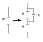
You can give a current spike to led ( component values is just taken for example )

Led_Curr_Limiter.jpg
 
Last edited:
  • Like
Reactions: sirwiz

    sirwiz

    Points: 2
    Helpful Answer Positive Rating
You can use a mosfet for T1 position.Then no need to sink/source current from the 4011.
 
  • Like
Reactions: sirwiz

    sirwiz

    Points: 2
    Helpful Answer Positive Rating
I never use mosfets in such circuit, which will be the best and i'll need just to switch t1 to mosfet transistor or modify somthing?
 

I think you can connect like this.
Replace t1 with a p-channel mosfet, Source sideshould be tied to VCC.
 

I tryed mosfet, but with no luck, there is some more power to the IR diode, but i lost data transfer.

You can give a current spike to led ( component values is just taken for example ) - im not quite wall understand this solution, can you tell me more about it, i can do it, but i always want to understand what im doing :)
 

Hi...
As you know, the output of the 4011 oscillator is a square wave.
This means that the duty cycle of the IR LED current is equal to 50% when Dout is on.
I downloaded the datasheet of LD271. On page 5, for pulses about 15us (as in your case) and a duty cycle = 50%, the permissible IF (forward current) is a bit higher than 300mA.
Based on your original circuit, you can test it as follows:
(1) Discoonect Dout from pin1 of 4011.
(2) Add a 10K resistor between pin1 and Vcc (12V).
(3) Run the circuit, you will get continuous pulses.
(4) by a DC voltmeter, measure the voltage (Vr) across R7 (47 Ohm)
(5) The LED peak current is equal to 2*Vr/47
(6) Now the power dissipated on R7 is around 2W.
(7) To increase the current you can add one or more resistors in parallel with R7, so I_LED = 2*Vr_new / R_equivalent

Note if you have another LED try to add in series with the first one. The current will be reduced but you can decrease the value of R7. In this case the dissipated power is less since some of the previous one is taken by the added IR LED. You may need to experiment the new distance range after using 2 LEDs... perhaps at some points they cancel each other... while at other points their signals are added.

Kerim
 

Oh, LD271 was only for testes now i use TSAL6100 or TSFF5210, but mostly TSAL6100 and i only use one.
 

For TSAL6100, in your case the peak of If is a bit more than 200mA (datasheet page 3).

For TSFF5210, it seems If max is 200mA for a duty cycle of 50%.

How long is the distance range you are looking for?

For instance, the brand of the IR receiver will play an important role in increasing the detection range.
Also, you may need to check the best carrier frequency (determined by 4011) that the IR receiver has the most sensitivity (when the carrier is at the center of its internal bandpadd filter). I think in your case, the carrier frequency is around 38 KHz (from the values of R5, R6 and C2).

Are you able to measure the IR carrier frequency?

Kerim
 
Last edited:

For now on this circuit on evning or night i can hit receiver with 52mm +8D lens from 100-200m. But for a day i havent got enougt power on led to break thru sun noise so range drop to 20m. I must hit receiver with focused beam in day from about 100m.
 

So adjusting (fine adjustment) of the TX carrier frequency is very important.

Are you testing it with no data? I mean on and off. If not, you can also try decreasing the data rate, this helps too, by a factor of 2 for example.

You may like to check the light spectrum of the IR LED and of the IR receiver. You know the IR spectrum is rather wide. So even both run in the IR region, it doesn't mean they work best on the light band.
 
Last edited:

I know. On 4 pin of 4011 i have 36.09 kHz, R5 for me is 10k? to adjust frequency.
 

Most IR receivers I knew like 38KHz... but you can fine tuning the oscillator resistor to get the longest range.

To lower the data rate (by a fator of 2) you can add another 10n at CTC pin. Obviously at the reception, the decoder data rate should be changed accordingly (you may need to check their datasheets; encoder and decoder).
 

In a receiver i use 4xtsop4836, its 36KHz for sure.
 

the last word is yours :) You know better than I what you have.

The datasheet says ... 36.7 kHz :smile:

On my side... the last word is the result of MY real tests :grin:
 

Really. How about IR receiver compatibility , is it capable to receive your transmitters carrier frequency.

I was late, You are discussing about it allready........
 
Last edited:

Hi;
A little bit late but;
tryed mosfet, but with no luck, there is some more power to the IR diode, but i lost data transfer.
You should also need to decrease the 47 ohm. Because with a rough calculation current on this line is (2 Volt forward for IR led) (12-2)/47 ~= 200 mA. Am i right?
This is also at the limits of the IR diode (TSAL6100) (ıf your pulse duty cycle is around 50%).
So you need a more powerfull diode and need to decrease R7 (47ohm) i think.
If your data bursts are less frequent you have chance to increase to current without damaging the IR led.
 

Any idea what MOSFET shoud i use, i only found n channel mosfets that suits in 100% this circuit requriments? I only tryed with one MOSFET that i have in home, so maybe thats why i cannot make it work with new part.
 
Last edited:

If you want to use N channel you should place it at the bottom side, see here and you need also invert the logic level to the gate (to drive current you should apply high signal to gate)
Some n channel mosfet parts BSH103, FDV305N.
 

I dont want to change to N type, i just cant find P type MOSFET, that will fit to this circuit. If i go to N i will do it on IRLD110PBF, as i understand what it need to do, this part will suit best to the led. But i cannot find P type transistor with similar parameters.
 

Status
Not open for further replies.

Part and Inventory Search

Welcome to EDABoard.com

Sponsor

Back
Top