Continue to Site

Welcome to EDAboard.com

Welcome to our site! EDAboard.com is an international Electronics Discussion Forum focused on EDA software, circuits, schematics, books, theory, papers, asic, pld, 8051, DSP, Network, RF, Analog Design, PCB, Service Manuals... and a whole lot more! To participate you need to register. Registration is free. Click here to register now.

Op-amp stability criteria confusion- unity gain of what?

Status
Not open for further replies.

Colon

Member level 3
Joined
Feb 1, 2010
Messages
66
Helped
1
Reputation
2
Reaction score
1
Trophy points
1,288
Location
England
Activity points
2,081
Hey there,

There have been a couple of similar questions before on this topic, but not exactly what I'm looking for.

So, having read the criteria from several sources, for an op amp to oscillate you need the following from the bode plot of the LOOP GAIN (ie. AB):
1) 180 degrees phase shift (from dc). Depending on the input you apply your ac source, this gives a phase of 180 (+ input) or 0 (- input) in the bode plot.
2) gain at the point of the 180 degrees phase shift.

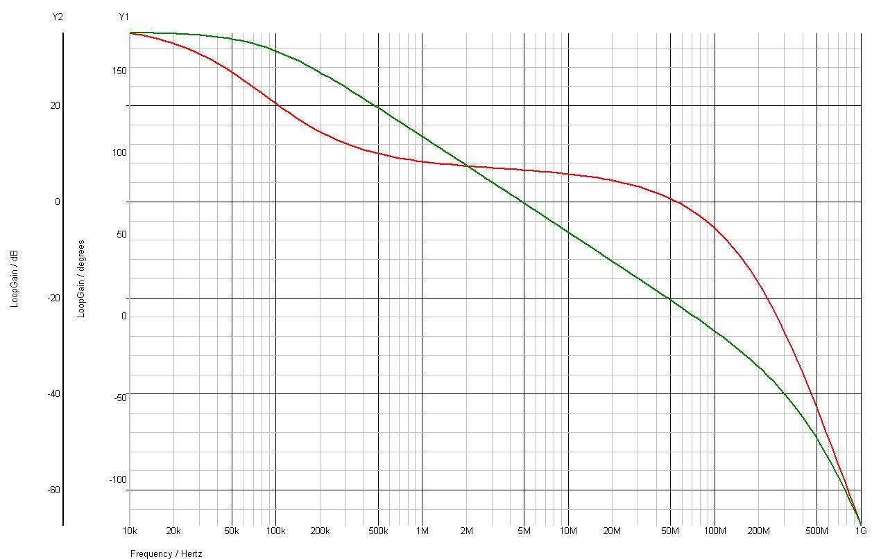
Ok, I have simulated my loop gain in spice by breaking the loop with a huge inductor, to maintain the dc conditions needed for the ac analysis to occur. I look at the bode plot and my loop gain drops off below unity at 5MHz. My phase doesn't reach 180 degrees til 200MHz, by which point the gain is down to -40dB. op amp stable right? Wrong, I have made this op amp (which has a fair amount of gain, 50dB) and it oscillates at 200MHz.

Even allowing for parasitics I don't see how this design can be simulated to be unstable. The bit that is bothering me is that the loop gain plot will continue to decrease if I increase my feedback resistor as B (=Rg/(Rg+Rf)) will decrease(increase my closed loop gain). If this graph decreases, it will cross the unity gain line at an even lower frequency, suggesting it will be even more stable. Yet, we all know increasing our closed loop gain will make an op amp less stable.

Something here is wrong, and I can't work out what it is. any ideas?

Thanks
James
 

So, having read the criteria from several sources, for an op amp to oscillate you need the following from the bode plot of the LOOP GAIN (ie. AB):
1) 180 degrees phase shift (from dc). Depending on the input you apply your ac source, this gives a phase of 180 (+ input) or 0 (- input) in the bode plot.
2) gain at the point of the 180 degrees phase shift.
...............
..............
James

James, I assume you have broken the ac loop with a large conductor at the opamp output, right?

Now my question: Why did you break the loop? This is necessary in order to inject the testsignal at one end of the inductor (via a large C) and to measure at the other end of the inductor (normally, opamp output).
However, if you connect the input voltage to the opamp input you never simulate the loop gain!.
Or did I misunderstanding something?
 

Yeah, I think I have done what you're suggesting. Immediately at the op amp output I have a 1GH inductor (!!), then the loop feeds back. My ac source connects at this point too (after the inductor), via a 1GF capacitor. Basically, see the spice model from this document, on page 9:

www.analogzone.com/acqt0214.pdf


My loop gain, AB, is take between nodes N3 and N2 in their diagram.

Thanks
James
 

That means your simulation arrangement seems to be OK. (You see, a circuit diagram can avoid misunderstandings from the beginning).

Another question: For negative feedback the phase response must start at -180 deg and go to -360 deg=0 deg.
Does your phase start with 0 deg ?


So here is my bode plot. As you can see, it starts at 180 degrees, as it should for this configuration. And you are therefore looking for the 0 degree point, which is around 200MHz.But here there is no gain. Also, you can see, that if the feedback resistor is increased, and B decreases, the loop gain decreases, the closed loop gain increases, yet form the graph the amp will be more stable, as the green line will fall. This is confusing me the most I think.
 

Yes, the BODE diagram looks perfect and stable.

But, what really is confusing you? That stability increases with rising closed loop gain (falling loop gain) ?

By the way: your sentence in the 1st posting (Yet, we all know increasing our closed loop gain will make an op amp less stable). is not correct. Are you aware of this?

Ok, is this where my understanding is wrong. Is it not the case that by applying negative feedback, and hence reducing the overall gain by forming a closed loop, that an op-amp will become more stable? If I am mistaken, this will explain what has been a major sticking point in my head, preventing me from fully accepting my simulation results. Of course, it would explain why I saw oscillations, though there is always parasitics, and even the change that it was actually pick up from something, that I saw. although, I did see multiple harmonics, which suggests to me that it isn't pickup.
 

I guess the problem originates from the term "stability" that has two different meanings:

* the dc stability of a circuit with dc feedback (that is the stability of the operating point against tolerances and temperatur influence) is proportional to the feedback factor - that means: large feeedback gives best stability.
Optimum case: unity gain feedback.
* However, at the same time the dynamic stability (against self-excitement, oscillations) reduces - that means: large feedback reduces this dynamic stability.
Most critical: unity gain feedback.

You see the difference?
 
Ok, this might be what has thrown me. So, as this is the case, I am willing to believe the simulation says that the op amp is stable. However, as I know there are some oscillations/pickups, I will investigate what exactly these are.

Thanks for your help.

James
 

What about capacitive loading of the real device or parasitic capacitances at the opamp input pins?
 

All sorted now. The amp doesn't oscillate. I also think I've gotten my head around simulating stability now so I'm good to go forward.

Next challenge is finding a way to stabilise the amp in a different configuration with low gain.... :)
 
Status
Not open for further replies.

Similar threads

Part and Inventory Search

Welcome to EDABoard.com

Sponsor

Back
Top