Continue to Site

Welcome to EDAboard.com

Welcome to our site! EDAboard.com is an international Electronics Discussion Forum focused on EDA software, circuits, schematics, books, theory, papers, asic, pld, 8051, DSP, Network, RF, Analog Design, PCB, Service Manuals... and a whole lot more! To participate you need to register. Registration is free. Click here to register now.

Labview and IIR filter explanation

Status
Not open for further replies.

ckshivaram

Advanced Member level 6
Joined
Apr 21, 2008
Messages
5,060
Helped
2,150
Reputation
4,306
Reaction score
2,088
Trophy points
1,393
Location
villingen (Germany) / Bangalore
Activity points
30,086


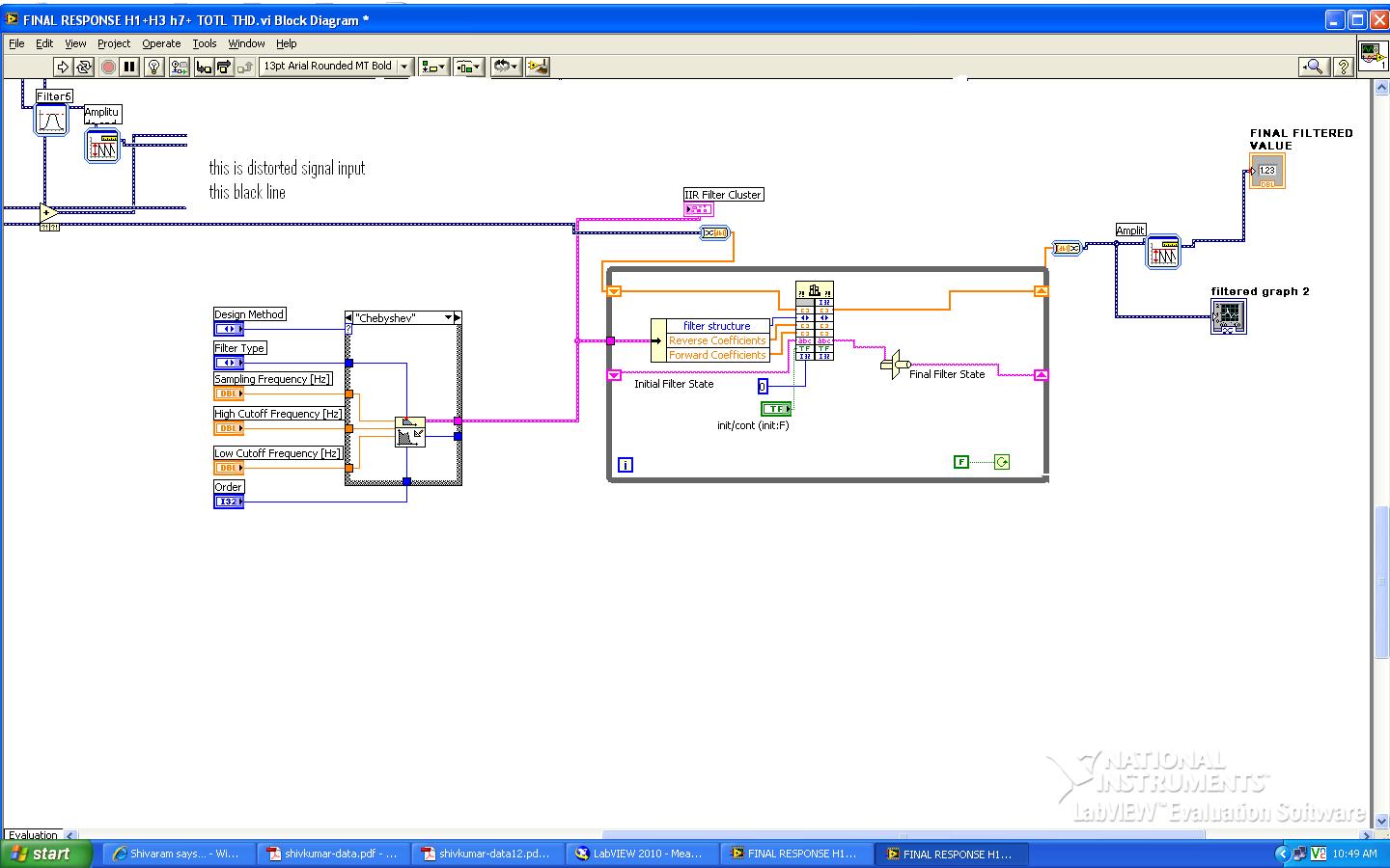
the output is perfectly correct...

this is the output of labview of a IIR filter. just wanted to know of how a iir filter will filter out the unwanted signal or distortion and finally produces pure signal.
i mean its band pass filter, its passes the signals inbetween the frequency 45hz to 65hz..

Anyone who can tell the logic of this output, and working.........
 
Last edited:

I'm not quite sure what you are asking. Are you asking "How does this VI work" ?

---------- Post added at 10:51 ---------- Previous post was at 10:44 ----------

Here is the LabVIEW Help (Chebyshev Filter VI - LabVIEW 2010 Help - National Instruments) on the Chebyshev Filter. It says that the input for Filter Type determines whether it's going to be a Bandpass, Bandstop, Highpass, or Lowpass filter. It appears as if you are creating your filter and then using those configuration components in conjuction with some dll (that is a Call Library Function Node in the middle there). I don't know what your dll does but it looks like it operates on the signal data only once (the While Loop's Stop Condition is set to let the loop only run once). The Final Filter State will be saved in the Shift Register between runs on the VI as long as the VI isn't closed (not in memory anymore). The other Shift Registers get reinitialized the next time the VI runs anyway. After running your data through your dll then you get the Amplitude of the data one last time and also display the filtered data on a graph. I hope this helps a little bit!
 
Hi thanks for the reply...

The output is perfect and since it is just drag and drop kind of working,, i could not understand how those filters worked... what could be the logic and code inside those blocks.
How iir filter will filter out the unwanted signal. Its procedure or its working logic ...
 
The Chebyshev filter is common among many places and LabVIEW just implements it normally (Chebyshev filter - Wikipedia, the free encyclopedia). I don't know what is happening inside of your Call Library Function Node but it appears to just be implementing the Chebyshev function because you are configuring a Chebyshev filter and then passing those configurations into it. Since it appears to be working correctly, then I just assume the dll is just working through the Chebyshev math to filter your signal.
 
Status
Not open for further replies.

Similar threads

Part and Inventory Search

Welcome to EDABoard.com

Sponsor

Back
Top