Continue to Site

Welcome to EDAboard.com

Welcome to our site! EDAboard.com is an international Electronics Discussion Forum focused on EDA software, circuits, schematics, books, theory, papers, asic, pld, 8051, DSP, Network, RF, Analog Design, PCB, Service Manuals... and a whole lot more! To participate you need to register. Registration is free. Click here to register now.

LED power/ charge indicator 2 different sources

Status
Not open for further replies.

vito51

Newbie level 6
Joined
Apr 7, 2011
Messages
11
Helped
0
Reputation
0
Reaction score
0
Trophy points
1,281
Activity points
1,357
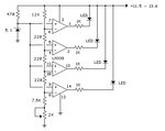
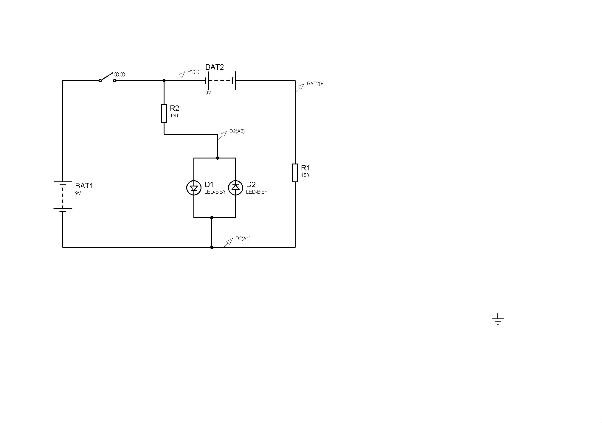
this may be a newbie question but ive searched for 2 hours and cant find anything quite like what im doing. i hope i have the right category. a little on what im doing. i am using a brushless motor (3phase) with a recitfier and a switching voltage regulator to charge a battery pack from a remote control car with the power from its gasoline engine. space is a problem or id just use a relay. what im trying to do is add a LED battery indicator using a bi color led. when the power switch is turned on, i want the led to light up one color being powered from the battery pack, when the gernerator is running and charging the battery pack the led would change color. and back once the generator stops. i could use 2 leds but i want it fancy. the voltage regulator will be set to 6.9v which is the voltage of a fully charged battery pack. how do i make it work, ive been loking at transistors, but can visualize it. i came accross comparators, but cant follow that either. im not an idiot, house wiring is easy beans to me, and i know a litle bit about IC stuff. am i peeing up a rope?
 

Attachments

  • voltage-comparator-circuit.gif
    voltage-comparator-circuit.gif
    3.4 KB · Views: 188
  • Like
Reactions: vito51

    vito51

    Points: 2
    Helpful Answer Positive Rating
yeah i found the lm339 in my search my brain way buzzing trying to follow the diagram. how do i know what size resistors to add?
 

Here is some ideas. Let's say that your genertor is rectified and we get DC from it and We have battery. I have attached to schematic. In the schematic consider BT1 as voltage from generator and BT2 as battery.


Thank You
 
  • Like
Reactions: vito51

    vito51

    Points: 2
    Helpful Answer Positive Rating
thats a good circuit, and would work perfectly but with 2 leds. which i may have to do. id like to use a bi color led which would need one of the supplies be disconnected from the led.
 

IF you are using 3 pin LED then you it should be trouble. Try shorting the Cathode of Bi-Colour LED with both the anodes in such that it will look like the above circuit. In simulation in works ok with some leakage of current to other LED but practically I haven't used ever. So you have to see.
Thank you
 

Attachments

  • 4.bmp
    355.1 KB · Views: 111
Last edited:
  • Like
Reactions: vito51

    vito51

    Points: 2
    Helpful Answer Positive Rating
Use something like above one
 

i dont see how it will turn off bat1 voltage to led when bat 2 is on?
 
Last edited:

i dont see how it will turn off bat1 voltage when bat 2 is on?

Switch is connected to BAT1 so this will be off as long as swtich is not closed. But when it is on then BAT2 will take voltage from BAT1 and stop at LED.
Since I don't find any kind of error in simulation I think it should work.
Thank you

PS: BAT2 is always on
 

You can try the following scheme.
1: you will need 2 transistors >> 1 pnp and 1 npn
2: Connect the base of both transistors to your comparator output/s. Use a resistor to limit the current.
3: Connect the collector of npn and emitter of pnp to the supply rail.
4: Connect the emitter of npn and collector of pnp to the bicolour led anodes. Use a resistor to limit the current.
5: Configure your connector in such a way that it gives you logic 0 when charging and logic 1 when charging or vice-verse, which-ever is comfortable. you can also use two comparators and connect the bases to either of the two.
6: Logic 1 will turn on the npn transistor. Logic 0 will turn on the pnp transistor.

Hope it helps.
 
  • Like
Reactions: vito51

    vito51

    Points: 2
    Helpful Answer Positive Rating
that makes more sense, thanks kapilp. im gonna bench test as soon as i ge thte parts thanx
 

Status
Not open for further replies.

Part and Inventory Search

Welcome to EDABoard.com

Sponsor

Back
Top