snaku
Junior Member level 3
Hi All,
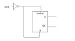
I have to design a circuit such that I have an input and I have to get complementary outputs. I am supposed to use D flip-flop and importantly with no clock. I have thought of doing it by only using preset(bar) and clear input and I do not use d and clk input. I have attached the circuit image. When input is high, the output is (Q=1, Qb=0) and when the input is low, the output is (Q=0, Qb=1).. Pllease, let me know if this works.
I have to design a circuit such that I have an input and I have to get complementary outputs. I am supposed to use D flip-flop and importantly with no clock. I have thought of doing it by only using preset(bar) and clear input and I do not use d and clk input. I have attached the circuit image. When input is high, the output is (Q=1, Qb=0) and when the input is low, the output is (Q=0, Qb=1).. Pllease, let me know if this works.