Continue to Site

Welcome to EDAboard.com

Welcome to our site! EDAboard.com is an international Electronics Discussion Forum focused on EDA software, circuits, schematics, books, theory, papers, asic, pld, 8051, DSP, Network, RF, Analog Design, PCB, Service Manuals... and a whole lot more! To participate you need to register. Registration is free. Click here to register now.

AD633 Multiplier Problem

Status
Not open for further replies.

syee10

Member level 3
Joined
Apr 2, 2010
Messages
63
Helped
1
Reputation
2
Reaction score
0
Trophy points
1,286
Location
Malaysia
Activity points
1,758
Hi,

I am designing a power meter which using the multiplier LM331 to multiply the Voltage and Current signal. The voltage and current signal will be go through the sample and hold circuit and the output of the sample and hold will be go into the LM331 multiplier. Power, P=VIcos(angle) and the LM331 having a transfer function of output W = [(X1-X2)(Y1-Y2)/10V]+Z. The problem is for example V=3V and I=2A, Output should be 6W(ignoring the cos(angle)). Due to the transfer function of LM331 i will never get the output 6W that i want. So anyone there can help me out? =)
 

mmm..did you used a LM331 or AD633? LM331 seems to be a V/F converter so i think it's useless.
On the contrary, AD633 is great and i used it for a programmable DC dummy load i made for testing power supplies. It was configured as you need, for calulating power, taking the input voltage and multiplying it for the current to get a constant-power drained independent from the input voltage.

The problem in your case could be that the inputs are multiplied each other, but then they are divided by 10. So, to get 6V as you want, you should put a X10 amplifier at the multiplier output or taking into account this scaling factor.

Bye
 

TomAss,

I having trouble connect the AD633 to get my power measurement. I connect exactly the same connection in Figure 11 "Basic Multiplier Connection". The input i give to X1 is 3V pulse, Y1 is 3V pulse, and X2 and Y2 i connected to ground. Z is connected to ground as well. The answer at W should be giving me 3X3/10 = 0.9 right? But instead of 0.9 i get a 12V at the output. I am sure the connection is no problem. Why is this happen? Please help me =(
 

Sure, it should perform as you said, getting 0.9V when driven with 3V for each input. On the contrary i could think the IC is broken. Had you tried to start with some simple tests, like connecting two pots, one to X input, the other to Y input, then looking what you get at the output for various input voltages?
The 3V pulses you apply are referenced to 0V ?
Please tell me more, if you can, about your application.

Bye
 

TomAss,

Can you teach me some more methods to test the IC is broken or still in good condition? Or any methods to get a 0.9V? Eg. i get a -0.9V first and i will invert it back to 0.9 or something?
The 3V pulse is a square wave clock pulse reference to 0V.
The purpose i using AD633 is because i want to get the power parameter from input voltage and input current. Eg. the input voltage is 3V and the input current is 3A. But in my case i am first using two similar input voltage 3V as my input for X and Y.
Please help me.Thanks.

Stephen
 

Of course you have to build the circuit as described by Analog Devices. Then you could stimulate the multiplier inputs with known voltages to see if at the output you get what you would expect.
For example, for the circuit drawn in fig. 11, assuming that X2, Y2 and Z are connected to ground, driving X1 with any voltage and keeping Y1=0, you should have no voltage at the output (the same if you swap X1 and Y1), then, driving X1 with 1V, you should get at the output 1/10 of the voltage applied to Y1.

If you drive X1 with 2V then you should have at the output 1/5 of the voltage at Y1.... and so on.

Needless to say that you should also check the correctness of supply rails,
the grounds and, with an oscilloscope, the output if any self-oscillation is present.
Having done this, if, for example, you put X1,X2,Y1,Y2 and Z to ground and still have 12V at the output, i think the AD633 should be dead.


There is no need to get a "-X" voltage then invert it, since this is a four quadrant multiplier and you have both noninverting "+" (X1/Y1) and inverting "-" (X2/Y2) inputs. So, for example, if your voltage reading was negative and you still wanted to have a positive output voltage, you should simply apply this negative reading to the "-" input instead of "+"...that's all.

What i don't understand is why you have square wave pulses for the current and voltage readings (?). Are you making impulsive measurements?

I don't know the degree of precision you would get, and the nature of your signals, but have you ever considered to use a microcontroller with internal A/D converter and having it to calculate the V/I multiplication?
An 8 pin Atmel Attiny could make the "miracle" with a quarter-dollar expense
(i said Atmel because i use them ... any other micro from Microchip, Freescale, NXP.... will do the job).

If you are designing a DC power meter, it will be easy to give the V and I samples
to the micro...if you are working with AC (what frequency?) it would be a bit more difficult, because you should design the precision full wave rectifier both for voltage and current measurement.
I suggest this solution also because i think it would be surely cheaper respect to using the AD633.

Last, if you are struggling with AC measurements so you have to cope with real and reactive power metering, have a look at Analog and Digital Processing ICs, Semiconductor Company, Cirrus Logic and their energy measurement chips or also Analog Devices | Semiconductors and Signal Processing ICs .
 
  • Like
Reactions: erikl

    erikl

    Points: 2
    Helpful Answer Positive Rating
TomAss,

Thanks for your reply. I definitely need an AD633 because i am building an energy meter actually. If this analog multiplier is working, then my whole project consider done. But this problems stuck for me 2 weeks already! I am damn sickening. I will try to connect it again tomorrow and see what's the result. If no, do you know any other low cost analog multiplier which has the same function as AD633? I am currently in malaysia and this AD633 only cost me around RM30 and this is acceptable for me. Microcontroller is not in my choice because just left this 1 part of circuit involving this analog multiplier then my project is done!
 

Hi Stephen,

ok..i suggested the micro because for me the AD633 was quite expensive.

Anyway, if you can find it easily and for you is cheap, i can really suggest to have the 633 working, because i was very happy when used it.
As you see, the basic circuit is so simple that it cannot not to work!
So there should be some nasty-stupid problem around.
When i used into my DC dummy load, i tested it on a breadboard, then when
i see that all was ok, i mounted it on the pcb...all worked...i had no problems.

Check the power supplies and make some DC tests (with two potentiometers
to give some reference voltages at the inputs) to see if it is properly working,
on the contrary consider substituting the IC with a new one.

Regarding other ICs, i used (in the audio field) old variable transconductance amplifiers like LM13700 and CA3080 as multipliers, but for what i remember they was quite temperature-dependent and, for sure, nastier to use and less performing respect to the 633 which is designed to be a "real" multiplier.

If you want to look for other components, consider Analog Devices or Burr-Brown (now part of Texas Instruments) as a source.

Have a nice weekend!
 
  • Like
Reactions: erikl

    erikl

    Points: 2
    Helpful Answer Positive Rating
TomAss,

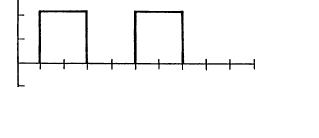
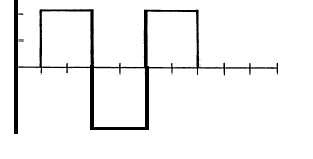
I already try out various way to check whether my AD633 is broken or spoil. The result i get is it is still functioning well. Im using square wave 1 to 8Vpp (signal waveform like in Figure 1 in attached file)to give the input to my X1 and Y1 while X2 and Y2 is grounded. The result i get is a little bit difference from the transfer function output of the AD633 by the way. This is still acceptable.
1 thing i dun understand is, when i apply a square wave without negative part, which i means a pulse of 50Hz frequency with 1-4Vpeak (signal waveform like in Figure 2), the output of the AD633 give me the wrong answer! No matter what is the value i give into my X1 and X2, the output will be still giving me 12.3V plus plus. The supply voltage i give to AD633 is +15V and -15V.
Is this means the AD633 must receive a square wave with positive and negative peak signal in order for it to functioning well? My input signal to the AD633 has to be same with the signal waveform as shown in Figure 2 in order to get the multiplication correctly. But if the AD633 cannot get this waveform for its input signal, what should i do? Should i use DC voltage to offset the signal in Figure 2 for let say +0.1V or -0.1V in order to shift my signal waveform in Figure 2 a little bit up or down?
I also notice that in Proteus simulation that i had done, the input signal into my AD633 in the simulation must have the similar waveform in Figure 1. If i set signal waveform just like in Figure 2 into AD633 in the simulation, there's an error and i cant get a result waveform.
Please comment. Thank you.

22_1300530190.png

76_1300530190.png
 

Ok now i found what is the problem already. This is funny problem and i really dun know why this happen. Forget about what i post in the previous post, regardless which type of square wave i put into my input X1 and Y1. Square wave with positive peak and negative peak or square wave with positive peak and 0 is working fine with the AD633.
The funny thing is, when i connect a probe (connect to oscilloscope) to either my input X1 or Y1, the output is working fine! And when i disconnect the probe again from my input X1 or Y1, the output is always show me 12.3V!! Why is this happen? Why must i connect a probe to either X1 or Y1 in order to get a correct output?! Please comment..
 

Hi Stephen,

maybe the 633 is unstable...this could be caused by poor supply decoupling (some 100nF capacitors from the two supply rails to ground mounted very close to the IC ) or any other reason that i don't know.
Can you see any high frequency signal superimposed to the output ?
On the contrary, it seems like X2 or Y2 inputs are floating though they must be grounded.
This could be caused also if X1 and Y1 are floating too (if they present high impedance in DC).


Anyway,by putting your oscilloscope probe from the input pins to ground, you could have done this:

-improved (or just connected) the ground on X2 or Y2 pins:
i don't know if you left the ground clamp connected to another ground point in the circuit or connected it to the Y2 or X2 pin. If you connected the ground clamp to X2 or Y2, through the oscilloscope, you put these pin to ground.
So check the proper grounding of these pins.

-added some small capacitance and high resistance between the X1 (or Y1) pin to ground...mmh..are you using some form of DC-decoupling (a series capacitor) from the square wave generator to the 633 input ? In this case, you should pull-down the 633 inputs adding a, say, 100K resistor from X1 or Y1 to ground. This will fix the DC potential at these pins to 0V and will not allow them to float in DC.

If you didn't see any oscillations at the 633 output i could think the problem is this latter.

I'm trying to guess what is happening because i don't know, except the figure 11 of Analog Devices datasheet, the rest of your schematic so how the 633 is driven.

Bye
Alessandro
 

I rather expect a trivial problem of missing ground connection or similar.
 

Status
Not open for further replies.

Part and Inventory Search

Welcome to EDABoard.com

Sponsor

Back
Top