DSNet
Newbie level 5
I am trying to create a circuit that allows me to digitally adjust the output voltage of a regulator using SPI.
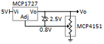
My current approach is to use an MCP1727 adjustable voltage regulator attached to a MCP4151 10kΩ digital potentiometer. Both the MCP1727 and MCP4151 are powered off of the 5V rail. My goal is to digitally control the output of the MCP1727 from 1.2V to 3.3V.
One problem I ran into is that I must prevent the voltage regulator from ever outputting anything higher than 3.3V which is possible under certain values given to the digital pot. In order to solve this, I plan on placing a 2.5V **broken link removed** between the output and the 0.8V adjust sense pin which should force the output voltage to never exceed 3.3V. With the diode, the circuit should be able to output between 1.2V and 3.3V properly since those voltages are not enough to trigger zener breakdown. If the voltage regulator momentarily outputs higher than 3.3V, the diode should conduct and ideally have zero resistance. This would set the R1/R2 ratio to zero and force the voltage regulator to output a lower voltage again.
I was wondering if anyone could verify my design. I have not bought any of the parts yet.
**broken link removed**