Welcome to our site! EDAboard.com is an international Electronics Discussion Forum focused on EDA software, circuits, schematics, books, theory, papers, asic, pld, 8051, DSP, Network, RF, Analog Design, PCB, Service Manuals... and a whole lot more! To participate you need to register. Registration is free. Click here to register now.
If you noted modem has received AT and it has responded OK (in your post 20); modem works well, no need to change it.
However PIC doesn't receive modem response, problem should be there. Check your max232 receiving side to PIC. (give manual input-signal from modem-side of max232 and monitor correct voltage on PIC side)
Did you use this max232 circuit when you connect PIC to PC ?
I have pull up(10K) to RX and TX pins. Max232 is in circuit.
The PIC is working fine with hyperterminal
Modem is working fine with hyperterminal
When I connect PIC with Modem...
I send "AT\n\r" to modem and receive "AT" which I am displaying on the 16x2 lcd display.
Along with this, I must receive \n\r as an indication that the modem is echoing the commands.
But, I am getting OERR bit high(RCSTAbits.OERR) which indicates that there is overrun error.
So, I am expecting that I am receiving data from Modem but couldnt properly hold it in RCREG.
I see you've totally disregarded my previous post (#14) saying to use "\r\n" instead of "\n\r" (some modems work fine with just '\n').
Also, overrun error implies you're not reading RCREG fast enough so the next byte comes and overwrites it. You're not getting "\n\r" because the modem probably responds with "\r\n", as I've been saying all along. (Notice that these are 2 distinct characters encoded as 0x0D and 0x0A, respectively.)
I didnt disregard your post. I have tried with both the options as \r\n and \n\r. In both the cases I am getting the same output. There is no change at all. So, I didnt mention it.
Yes...I am not able to read the RCREG fast enough. I am trying to resolve that only.
Hi...
Actually, there was a problem with overflow error in Receiving.
When I connected pull ups to PIC, I started receiving proper characters(without pull up it was garbage).
I had used both TX and RX as low priority intr. So, even when I received the data on RX pin as an echo of TX, RX intr was not generated and finally OERR bit was set loosing the response of Modem.
Now, I changed the RX to High priority intr and its working.
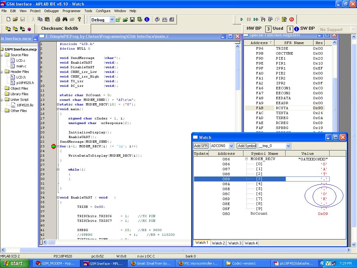
I have attached the image where the received data is shown in buffer.
I however have a small problem now and tht is, how to implement FIFO dynamically in Receive intr.
I read about circular buffer, ring buffer but they are very complex. I am scared of it.
Is there any simple solution available for FIFO implementation?
I’ve been implementing circular buffers in all kinds of flavors and purposes for years now and only with positive results. I think you can’t do serious communication without them!
A circular buffer is the best solution for your problem and for your particular case it’s very easy to implement, so there’s nothing to be scared about.
You declare your buffer as a regular array of bytes, and 2 pointers to byte that will point to elements of this array (or you can just use indexes if you don't like pointers). One pointer is for writing bytes in the array (used by the UART ISR, server, producer etc.) and the other one is for reading bytes from the array (used by the main loop, client, consumer etc.).
A) Initialize both pointers to point to first element of the array. The buffer is then empty. B) On the producer side (ISR):
- write a byte to where the write-pointer points;
- increment write-pointer;
- if it points after the end of the array, you make it point to the beginning (that’s why it’s called “circular”);
- [optional] if it points to one location less than the read-pointer, the buffer is full (you can skip this test and continue by overwriting). C) On the consumer side (main loop):
- if the read-pointer points to the same location as the write-pointer the buffer is empty, there’s nothing to read;
- otherwise read the byte pointed to by read-pointer;
- increment read-pointer;
- if it points after the end of the array, you make it point to the beginning (that’s why it’s called “circular”).
Of course, all rules for working with interrupts apply here too (volatility, critical resource access etc.), but otherwise there’s nothing much to it, as you can see.
This site uses cookies to help personalise content, tailor your experience and to keep you logged in if you register.
By continuing to use this site, you are consenting to our use of cookies.