Continue to Site

Welcome to EDAboard.com

Welcome to our site! EDAboard.com is an international Electronics Discussion Forum focused on EDA software, circuits, schematics, books, theory, papers, asic, pld, 8051, DSP, Network, RF, Analog Design, PCB, Service Manuals... and a whole lot more! To participate you need to register. Registration is free. Click here to register now.

Pulse Generator (Pleas help me on the project)

Status
Not open for further replies.

nazmul6078

Newbie level 6
Joined
Mar 20, 2009
Messages
11
Helped
0
Reputation
0
Reaction score
0
Trophy points
1,281
Activity points
1,363
Hi all,
I need your help. I try to do this project of pulse generator for more than six month :-( .But could not figure out.

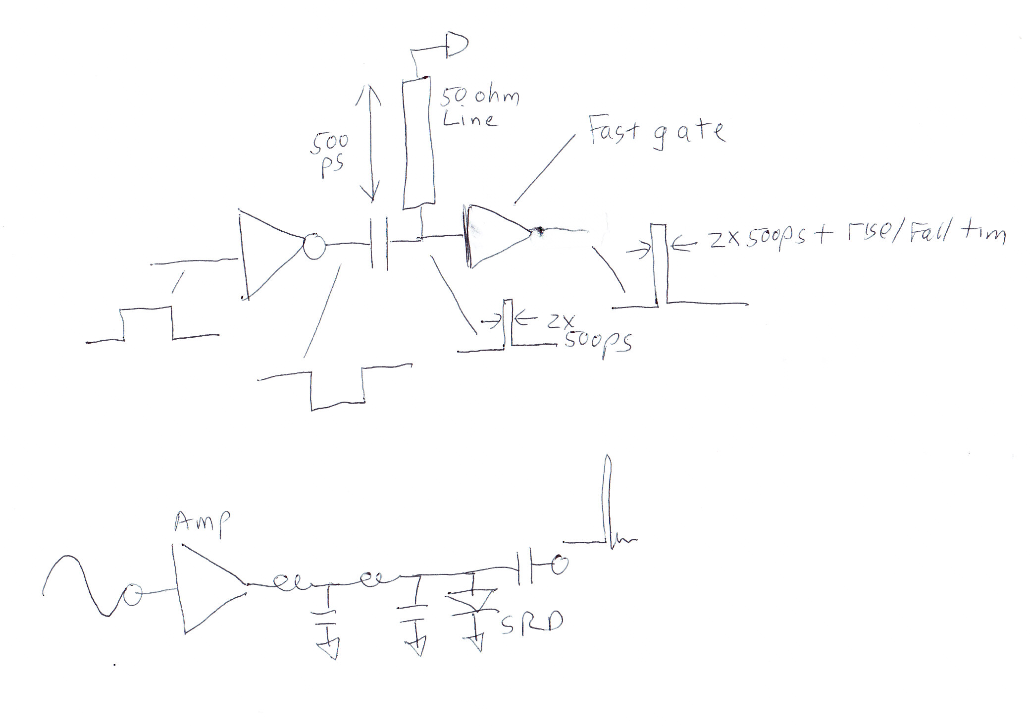
Pulse shapes are included in the attached file.
any of the three shape is okay. First one (Fig. 1 (a)) is better. Frequency / duration is just approximation. Tunable option is more preferable.

and also share your Ideas how i can generate and detect these kind of pulses.

P.S...I am not expert on micro-controller :-(
 

Attachments

  • figure_for_pulse_circuit.pdf
    29.1 KB · Views: 156

I'm Not a expert in the subject but the third looks like some form of On-Off Keying

The idea on on-off keying is that the transmitter is on when logic 1 is transmitted and the transmitter is off then logic 0 is transmitted.
OOK modulation has the advantage of allowing the transmitter to idle during the transmission of a zero.

You can consider OOK to be as a special form of amplitude modulation. Here input signal has two states (1 and 0) and modulation factor is 100% (from full power to no transmitted power).

The circuit plans for amplitude modulation (AM) should work here on both ends. The transmitter end can be generally simpler than generic AM modulator. The receiver can be a normal AM detector forllowed with a voltage comparator (if AM demodulator input is higher than certain set reference, output is logic 1, otherwise logic 0).

OOK is for example used in IR remote controllers where the 36 kHz IR signal is modulated on/off depending on control data. Also some simple optical fiber communication applications use OOK (transmitter LED if on or off).
 

There are two fairly easy ways to generate the monopulse. 1) have a square wave drive a gigabit logic digital gate. AC couple into the gate, and have a shorted length of transmission line attached there too. The square wave turns into a very short pulse, and the gate acts as a buffer amp.
2) have a high power (300 mw) sine wave drive an impulse generator. The impulse generator is a series inductor attached to a shunt mounted step recovery diode. Additional input matcing and output highpass filtering helps efficiency.

For receiving, the lowest cost way is to use a "sampler circuit" and use "equivalent time sampling". This is the way oscilloscopes in the 1970's were able to display microwave signals--they used a fast input sampler hooked up to a 100 MHz oscilloscope, and just sampled the input over and over again until they saw the waveshape. Impulse radars typically vary the sampling time by using a ramping analog voltage and some comparator circuits.

Hi biff,
I try to understand what you are saying. But I didn't catch you. Can you draw me a picture or any kind of link related circuit.
I dont understand [1]
For [2] as far as i understand you are talking about the SRD.
Please give me some ref/ picture or whatever you have, including the name of the ics.
I appreciate your help.

---------- Post added at 04:09 ---------- Previous post was at 04:07 ----------

I'm Not a expert in the subject but the third looks like some form of On-Off Keying

The idea on on-off keying is that the transmitter is on when logic 1 is transmitted and the transmitter is off then logic 0 is transmitted.
OOK modulation has the advantage of allowing the transmitter to idle during the transmission of a zero.

You can consider OOK to be as a special form of amplitude modulation. Here input signal has two states (1 and 0) and modulation factor is 100% (from full power to no transmitted power).

The circuit plans for amplitude modulation (AM) should work here on both ends. The transmitter end can be generally simpler than generic AM modulator. The receiver can be a normal AM detector forllowed with a voltage comparator (if AM demodulator input is higher than certain set reference, output is logic 1, otherwise logic 0).

OOK is for example used in IR remote controllers where the 36 kHz IR signal is modulated on/off depending on control data. Also some simple optical fiber communication applications use OOK (transmitter LED if on or off).

yes ON-off keying doing this job..do you know any IC's number or any picture or link.
Thanks for your time.
 

Your signal seems to have a frequency of 10Mhz, the best I could get was 75Mhz http://www.analog.com/static/imported-files/data_sheets/ADF7012.pdf so you may need to design a generating circuit if frequency constraints are strict.

However the detector should be okay **broken link removed**

Here is some nice reference **broken link removed**
 
Those pulse shapes are somewhat similar to what we use in MRI sequences. We generally synthesize them by starting with a sine wave coming from a DDS chip. Then we mix it with our desired envelope. Depending on the power/distortion requirements, we can mix using a simple diode mixer, a voltage controlled amplifier, or a variable gate bias power amplifier. The only limitation of this is that the carrier frequency is fixed within each pulse (no sweeping frequency).
 
The envelope shape hasn't been exactly characterized, but I think, the waveforms can be basically generated by sending a gated 100 MHz squarewave to a bandpass filter with variable Q. Only the third waveform, a sine wave exactly switched at the zero crossings cant' be generated this way, it would need an analog gate behind the filter.

As said by John Connor, a sine generator (e.g DDS) with a programmable analog modulation can do in a more flexible way, but with higher effort.

Finally, a modern arbitrary function generator with sufficient sampling rate can.
 

Right, if you really wanted to do any waveform, then you'd just build an arbitrary waveform DDS with a DAC and FPGA. The frequency would be limited by nyquist though.
 

Status
Not open for further replies.

Part and Inventory Search

Welcome to EDABoard.com

Sponsor

Back
Top