Continue to Site

Welcome to EDAboard.com

Welcome to our site! EDAboard.com is an international Electronics Discussion Forum focused on EDA software, circuits, schematics, books, theory, papers, asic, pld, 8051, DSP, Network, RF, Analog Design, PCB, Service Manuals... and a whole lot more! To participate you need to register. Registration is free. Click here to register now.

[SOLVED] Acitve loop filter for PLL

Status
Not open for further replies.

vfurlan

Full Member level 2
Joined
Mar 27, 2006
Messages
133
Helped
10
Reputation
20
Reaction score
2
Trophy points
1,298
Location
Slovenia
Activity points
2,185
I designed a active filter for PLL but the loop is out of lock.
Parameters of my PLL-VCO are

VCO gain Kvco = 60 - 80MHz/V
Phase detector gain Kv = 0.32 rad/V
loop bandwidth Fc = 10 000Hz
N = 22
φ = 45
I'm using AD 8622 OP-AMP.

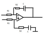
R1 = 312kΩ (used 330k)
R2 = 15.9k (used 15k)
C = 1nF

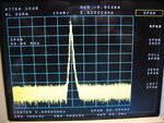
I use a 250MHz signal and N = 22, so VCO oscillates at 5.5GHz.
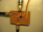
On schematic.png is a filter design, on filter.jpg you can see my filter, and on 5903.jpg the VCO respons.

Can you advise me what to do?
Thank you
 

Attachments

  • IMG_5903.JPG
    IMG_5903.JPG
    3.1 MB · Views: 174
  • SCHEMATIC.png
    SCHEMATIC.png
    5.7 KB · Views: 176
  • Filter.JPG
    Filter.JPG
    2.3 MB · Views: 182

Perhaps PLL locked. Try to see an spectrum at small span. Resistor values are very big. So VCO noise can degrade essetial.
 

    V

    Points: 2
    Helpful Answer Positive Rating
1. AD8622 need dual power supply, if you only use positive power supply, the noise is very big. And AD8622 noise is very huge, you should select another one.
2. The power supply need Tan capacitor to filter.
3. The grounded system are not good. For power supply and OpAmp, grounded is very important. You vias is too few.
4. You can use ADISimpll free software to simulate before you do it.
 

    V

    Points: 2
    Helpful Answer Positive Rating
It seems your filter is not close to the PLL. I dont't think is a good idea since pulses from charge pump, travelling on coaxial cable, are both delay and distorted (the impedances are not matched) of a quantity depending from the cable length. Even if distortion is negligible, excessive delay could drive the PLL into instability.
First of all you could try to shorten as much as possible the cabling. However I think you should also implement the suggestion of tony_lth, mainly the dual supply and te Tan capacitors on the power supply rails. Could you post the complete schematic with cables length and the spectrum with a narrower span (hundred of KHz) because it seems you have a groups of raws superimposed on the carrier ?
 

    V

    Points: 2
    Helpful Answer Positive Rating
1. AD8622 need dual power supply, if you only use positive power supply, the noise is very big. And AD8622 noise is very huge, you should select another one.
2. The power supply need Tan capacitor to filter.
3. The grounded system are not good. For power supply and OpAmp, grounded is very important. You vias is too few.
4. You can use ADISimpll free software to simulate before you do it.

Thak you for suggestion, I will try.
Can you suggest a suitable OP AMP? One with better noise.
 

ADA4841, single power with very low noise.
 
ADA4841, single power with very low noise.
I made the connections short, added dual supply, but it didn't made much differenc e (maybe a little). SO I have to change the OPAMP.
What do you think about AD8675? I need 15Vsupply. ADA4841 is only up to 12V.
 

If you don't ground well, nth can do except making a new layout.
And you should do albbg said, make in PLL + VCO + Amp in one PCB.
And you can use LDO for power supply.
AD8675 is good, but AD797 is better in noise and worse in spur. You can make a tradeoff.
Good luck.
 

are you sure you do not have any more R-C components in the schematic? My calculations show you have an open loop bandwidth of 50 KHz and a phae margin of 78 degrees. So it should be stable.

If you had additional series R and shunt C components, either in front of the op amp, or between the op amp and vco, they would add more phase shift and maybe make it unstable.

If not, I would make sure there are good bypass capacitors on the voltage supply lines right next to the op amp. modern op amps, with their huge bandwidths, LOVE to oscillate.

BTW, it is a really good idea to have perhaps a 220 ohm resistor between the op amp output and the VCO tune port, to protect the varactor from blowing up.
 

Attachments

  • Doc3.doc
    27.5 KB · Views: 147
Last edited:
My calculations show you have an open loop bandwidth of 50 KHz and a phae margin of 78 degrees. So it should be stable.

Hi, biff44,
I want to ask a basic question. How can you calculate the open loop bandwidth and phase margin?
 

are you sure you do not have any more R-C components in the schematic? My calculations show you have an open loop bandwidth of 50 KHz and a phae margin of 78 degrees. So it should be stable.

If you had additional series R and shunt C components, either in front of the op amp, or between the op amp and vco, they would add more phase shift and maybe make it unstable.

If not, I would make sure there are good bypass capacitors on the voltage supply lines right next to the op amp. modern op amps, with their huge bandwidths, LOVE to oscillate.

BTW, it is a really good idea to have perhaps a 220 ohm resistor between the op amp output and the VCO tune port, to protect the varactor from blowing up.

No, I do not have any other components.
 

Well, I would seriously look at the op amp itself as a source of oscillation. Do you have nice bypass caps on the + and - rails, like a 1 uF ceramic? Probe the + and - supply leads right at the op amp and see if there is an oscillation there (it should be flat dc with maybe no more than a few tens of mv of ripple). Similarly, the VCO itself needs bypass capacitors on the +V supply rail.

Are you sure you are programming the pll right? If you think you are setting up N=22, but instead have a different divisor that puts the VCO outside of the frequency range it can legally tune to, it will sit there open-loop. You can often get a clue to this happening if the Vtune line is up near the supply rail, where the op amp may no longer have any gain.

How do I calculate the parameters? I set up an equation in mathcad with complex VCO transfer function (KV/s = (2*pi*70x10^6)/s ), phase detector transfer function (Kd), gain of the divisor (1/N), and the complex tranfer function of the op amp G1 = (1+R2C2s)/(R1C2s), all multiplied together. Then just plot the magnitude and phase of the equation. The comparison frequency here is so high that there is not much time delay in the divider, so you can ignore the transport lag (extra phase shift) of the divider in this case. The phase shift graph starts off with the phase shift of 2 poles (the op amp and the vco, for -180 degrees). At the zero frequency (around 9 KHz) the zero adds around +45 degrees to it (and the gain slope changes from 40 dB/decade to 20 dB/decade). s=j2*pi*f

Rich
 
Last edited by a moderator:
that would make it less stable than it already is supposedly designed for.

When the phase hits -180 at 0dB crossover, it is guaranteed to oscillate.
 

yes, biff44, you are right.
But according to my experience, it's better to set phase margin at 45 deg, because less margin have better phase noise.
See the following two pictures, I simulated with ADIsimPLL free software from Analog Devices.
When 45 deg, PN=-115dBc/Hz@100KHz; when 84 deg, PN=-103 dbc/hz@100KHz.
 

Attachments

  • phase margin 45deg.JPG
    phase margin 45deg.JPG
    38.3 KB · Views: 143
  • phase margin 84deg.JPG
    phase margin 84deg.JPG
    30.7 KB · Views: 143

True, I agree. Also, setting the phase margin closer to 45 degrees will give better settling time. I personally like 60 degrees as a design margin.

But, the original poster can't get his loop to lock. So there are probably other issues, and making the thing uber stable is a good first step!
 

I changed OpAmp, now I'm using AD8675. I have a nice 1uF capacitors at + and - power supply. Same filter as before. Now I'm using Minicircuits ROS-2800-719+ as VCO, on my own PCB. VCO is good.
Whet it locks it looks ok, but it locks at 1300MHz ONLY. If I have N = 22, it locks a 59MHz RF signal supply, if I hace N = 21, it locks at 62MHz!!! What is happening?
 

Depending on the phase detector type and filter bandwidth, the lock range will be possibly limited. What's the involved phase detector?
 

When it is not locked, what is the tuning voltage going to the vco. If it is less than 0V, you could be making the vco flip out.

Are you sure it is really locked? When N=22 and VCO is locked at 1300 MHz, if you change the clock frequency from 59 to 59.01 MHz, does the VCO change from 1300 to 1300.1 MHz?

And what are your power supply voltage(s)?
 
Last edited:

Status
Not open for further replies.

Similar threads

Part and Inventory Search

Welcome to EDABoard.com

Sponsor

Back
Top