Continue to Site

Welcome to EDAboard.com

Welcome to our site! EDAboard.com is an international Electronics Discussion Forum focused on EDA software, circuits, schematics, books, theory, papers, asic, pld, 8051, DSP, Network, RF, Analog Design, PCB, Service Manuals... and a whole lot more! To participate you need to register. Registration is free. Click here to register now.

HFSS setup of array patch

Status
Not open for further replies.

ae6

Newbie level 3
Joined
Dec 17, 2009
Messages
3
Helped
0
Reputation
0
Reaction score
0
Trophy points
1,281
Location
engineering
Activity points
1,301
Hi,
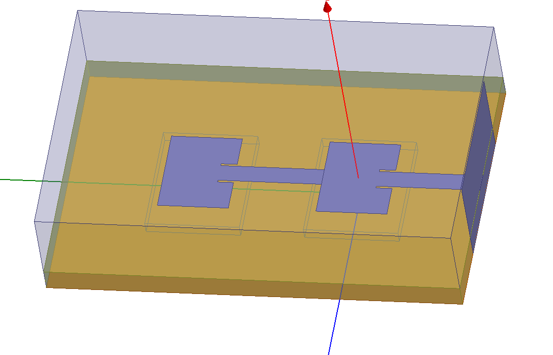
i design an array patch.
what setups should be added?(only array setup in radiation ?)
TNX.
 

It depends on what kind of characteristics you want to observe.

If your array has only one feed point, nothing special is needed for your setting. The process is the same with simulating a single patch.

Just do the rigth thing on boundary and excitation setting, and then you can get the correct results.
 

hello Shmily,

I have a rectangular one patch and I'm not sure how to do the array... I want to actually see my design like multiple patches and stuff because i don't understand the array setup..

Please help
Thanks,
sam
It depends on what kind of characteristics you want to observe.

If your array has only one feed point, nothing special is needed for your setting. The process is the same with simulating a single patch.

Just do the rigth thing on boundary and excitation setting, and then you can get the correct results.
 

Hey,

I believe what you want to do is apply master-slave boundary conditions to your radiation space. These will make the electric field the same on the master and slave boundary within a given phase delay. It is HFSS's way of implementing a periodic structure without actually simulating many elements.

For more detailed information on master-slave boundaries, look here:
Ansoft Presentation

I've seen endfire antenna arrays simulated in this manner. They placed master-slave boundaries on the radiation box that is above the opening to the antenna to simulate this. I believe you should be able to do something very similar with a patch antenna.
 

hello Tranquiltension,

Can you please look at my design? I can send you my one patch to your email if that help! I'm trying to duplicate this one patch with a half wave length between the patched and I'm not sure how??? Can you please let me know the steps in how to do so? I couldn't find any info online and I'm in contact with Ansoft help desk to support me in this but it's taking a long time! I'm trying to develop an array on one axis like one line of patches all in one axis and I'm unable to do so! Please let me know if you have any information about this?

Thanks again,
Sam

Hey,

I believe what you want to do is apply master-slave boundary conditions to your radiation space. These will make the electric field the same on the master and slave boundary within a given phase delay. It is HFSS's way of implementing a periodic structure without actually simulating many elements.

For more detailed information on master-slave boundaries, look here:
Ansoft Presentation

I've seen endfire antenna arrays simulated in this manner. They placed master-slave boundaries on the radiation box that is above the opening to the antenna to simulate this. I believe you should be able to do something very similar with a patch antenna.
 

Hey-

You should be able to accomplish this by adding master-slave boundaries on only two edges. The master-slave boundary will extend the structure infinitely in the directions of the normal vectors of the surfaces that are being used as master-slave.

A few things to note about master-slave boundaries: They must fall on planar surfaces and you must provide U,V vectors. These define the coordinate system for the master-slave boundaries.

Please read the link I posted. It has a small section on master-slave boundaries that is quite helpful.
 

Hello tranquiltension,

I'm not sure if the master/slave boundaries will work because I have an inset fed in my patch antenna? Do you think this will work? I'm really trying to follow what the tutorial say about the sizes of the master and slave should be identical but when I combined those patches through the inset fed I don't get an identical shape! They might be a little off!
Please let me know if this OK??

Thanks,
Sam
Hey-

You should be able to accomplish this by adding master-slave boundaries on only two edges. The master-slave boundary will extend the structure infinitely in the directions of the normal vectors of the surfaces that are being used as master-slave.

A few things to note about master-slave boundaries: They must fall on planar surfaces and you must provide U,V vectors. These define the coordinate system for the master-slave boundaries.

Please read the link I posted. It has a small section on master-slave boundaries that is quite helpful.


---------- Post added at 18:40 ---------- Previous post was at 18:19 ----------

Hello again Tranquiltension,

Probably i didn't make sense but I made a simple drawing to make you understand what I'm trying to do.. hopefully you can help me out in this?
26_1295631345.png


Thanks
sam

Hello tranquiltension,

I'm not sure if the master/slave boundaries will work because I have an inset fed in my patch antenna? Do you think this will work? I'm really trying to follow what the tutorial say about the sizes of the master and slave should be identical but when I combined those patches through the inset fed I don't get an identical shape! They might be a little off!
Please let me know if this OK??

Thanks,
Sam
 

Hey Sam,

If you're only trying to simulate two patches, you might want to try simply using the symmetry planes. Master/slave boundaries are for replicating periodic structures - ie: arrays of antennas in one or two dimensions. If this is what you're going for, you should be able to draw another vacuum box around your antenna and part of the feed - you say you want the periodicity to be lambda/2, make the box that big and make sure to include the whole patch. Then apply master-slave boundaries to that box.

I haven't used symmetry planes yet, so I'm afraid I'm of no help if that's what you're going for...
 
Hello Tranquiltension,

Sorry to bother you again but I'm trying to add multiple patches to my array (one dimensional / on the same axis)! Those two patches are just a start! I was wondering if you can help out b/c I'm getting really low gain on 1x4 array like 0.23 whereas i was getting about 3 in my one patch... I'm sure im doing something wrong but I'm not that familiar with HFSS and their support line is not responding!

Thanks,
sam

Hey Sam,

If you're only trying to simulate two patches, you might want to try simply using the symmetry planes. Master/slave boundaries are for replicating periodic structures - ie: arrays of antennas in one or two dimensions. If this is what you're going for, you should be able to draw another vacuum box around your antenna and part of the feed - you say you want the periodicity to be lambda/2, make the box that big and make sure to include the whole patch. Then apply master-slave boundaries to that box.

I haven't used symmetry planes yet, so I'm afraid I'm of no help if that's what you're going for...
 

Does anyone know how to calculate the ground plane ?
and how to find the coordinat in HFSS ?

Thanks
 

Status
Not open for further replies.

Part and Inventory Search

Welcome to EDABoard.com

Sponsor

Back
Top