Continue to Site

Welcome to EDAboard.com

Welcome to our site! EDAboard.com is an international Electronics Discussion Forum focused on EDA software, circuits, schematics, books, theory, papers, asic, pld, 8051, DSP, Network, RF, Analog Design, PCB, Service Manuals... and a whole lot more! To participate you need to register. Registration is free. Click here to register now.

anyone have a pin diode linearizer schematic handy?

Status
Not open for further replies.

biff44

Advanced Member level 6
Joined
Dec 24, 2004
Messages
5,047
Helped
1,376
Reputation
2,748
Reaction score
1,056
Trophy points
1,393
Location
New England, USA
Activity points
37,909
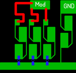
Been searching around and did not find a simple schematic, and I'm too tired to reinvent the wheel! Need to take 0 to +10 V control in, and drive 4 microwave pin diodes spaced quarter wave apart to get a linearized Vin vs. dB attenuation. Will take either a breakpoint linearized or log driver.

Thanks, Rich
 

Here is HSMP-3816 Application. I don't know whether it will help you or not.
 

Attachments

  • HSMP-3816 Application.pdf
    98.7 KB · Views: 148

No Tony, I am looking for the op amp driver circuit that drives the microwave portion.

I did find this one:

**broken link removed**

The last diagram on the page looks promising, but it looks unnecesarrily complex. I was hoping to do the same thing with one op amp and one transistor! That diagram also probably needs some speed-up capacitors around the output transitor.

Rich
 
maybe you can use HMC346 and ...
 

Attachments

  • Bipolar Attenuator.jpg
    Bipolar Attenuator.jpg
    32.6 KB · Views: 220
  • HMC346LP3 Voltage Control Atten.jpg
    HMC346LP3 Voltage Control Atten.jpg
    54 KB · Views: 183

Do you mean something like this?
Sign under the figure in Russian means: the schematic of the absorbing ladder type attenuator with a certain law of change of diodes resistance.
Left connector is input.
 

Attachments

  • att.gif
    att.gif
    9.1 KB · Views: 156
Yes Ledum, that is the microwave structure I am trying to drive. I have 4 pin diodes, and they are all fed from one common bias point. I need to take a control voltage input, and convert it to a diode driving current so that dB Insersion Loss is propostional to Vcontrol input.

Tony, that is a good circuit, but the HMC device is a FET based switch (voltage controlled), so I am not so sure that driver will work with a PIN diode attenuator.
 
Last edited:

Hi, biff44,
HMC346LP3 is a voltage-variable attenuator, I think if use HMC346LP3E, you don't need use PIN diode any more. Attached is HMC346 voltage vs. attenuation. But I don't know what's your requirement on phase.
 

Attachments

  • HMC346LP3E.JPG
    HMC346LP3E.JPG
    22.9 KB · Views: 127

We used topology like at attachment (alumina 0.5mm, resistors - tantalum thin film 50 ohms per square). Diodes were old soviet 2A533A-3 p-i-n diodes (all sizes in mm, Cd=0.05pF, Ubr=70V). Control law was very close to the linear. Regulation range at Vmod 0-12V (current 0-100mA) was 35dB for 4 diodes configuration in half-octave band near 12GHz. Loss at 0V control voltage was something like 1.5 dB. But, it was 25 years ago. I think tony_lth is right about HMC346LP3
 

Attachments

  • mod.png
    mod.png
    10.1 KB · Views: 122
  • 2a533.gif
    2a533.gif
    13 KB · Views: 123
Last edited:
maybe you can use HMC346 and ...

I have the above HMC346 + opamp circuit somewhere already milled onto a PCB. I tested this circuit a few years ago.

I don't recall it being that linear in terms of Volts vs attenuation. Also the control V vs attenuation was a bit iffy over temperature on the higher attenuation settings.

But it was still a useful attenuator :)
 

I guess biff44 need control circuits between detector and attenuators, not RF circuits.
 

Status
Not open for further replies.

Part and Inventory Search

Welcome to EDABoard.com

Sponsor

Back
Top