Continue to Site

Welcome to EDAboard.com

Welcome to our site! EDAboard.com is an international Electronics Discussion Forum focused on EDA software, circuits, schematics, books, theory, papers, asic, pld, 8051, DSP, Network, RF, Analog Design, PCB, Service Manuals... and a whole lot more! To participate you need to register. Registration is free. Click here to register now.

Measuring input common-mode range

Status
Not open for further replies.

thanhtri_pc

Junior Member level 2
Joined
Apr 18, 2010
Messages
22
Helped
0
Reputation
0
Reaction score
0
Trophy points
1,281
Location
Vietnam
Activity points
1,458
Hi all,
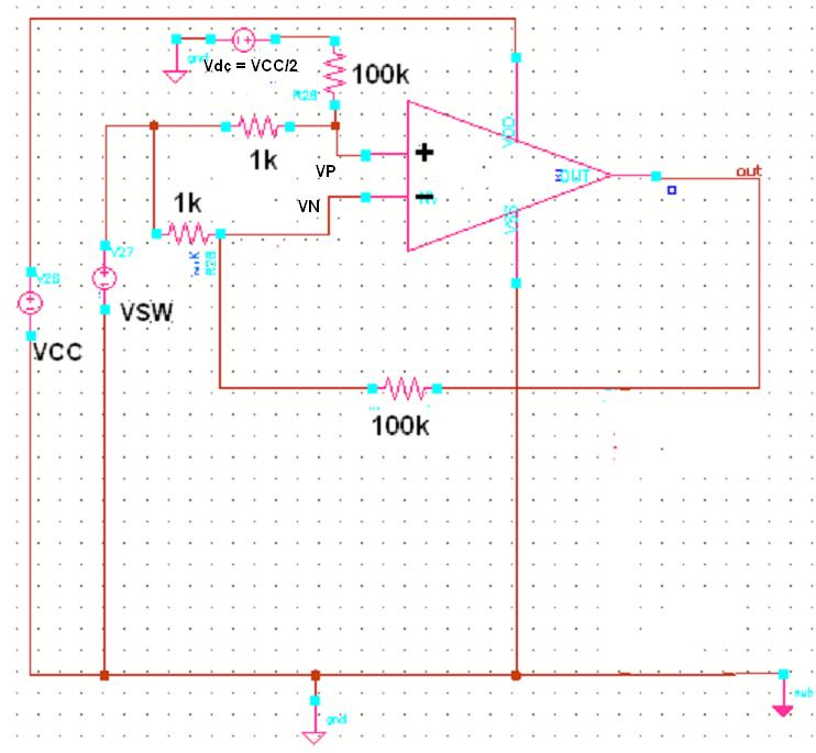
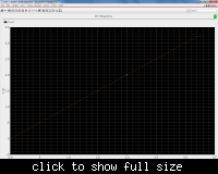
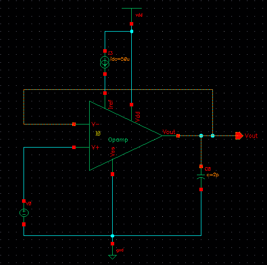
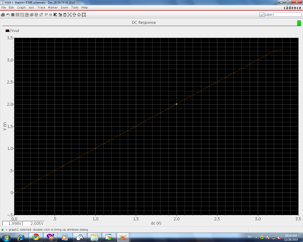
I just designed an op-amp and I want to characterize this op-amp. First, I measure the input common-mode range. I draw the the schematic and run DC analysis. I get result as attached picture.

Specification: Vdd = 3.3V, Vss = 0V, V- and Vout are connected together, V+ is swept from 0v to 3.3v.
Please show me how to extract Vinput(max) and Vinput(min)?
Many thanks


for this setup sweep VSW from < 0V to >VDD , the range where the difference of vp-vn is flat u can consider as the ICMR of the opamp(refer the plot)
 

Thanks for your consideration.
As you see in figure above. This schematic show that Vout exactly equal to Vp, so we can imply that Vp = Vn. Therefore, if Vic(min) <= Vp <= Vic(max), Vp = Vn and Vp-Vn = 0. Other word, I configured my Op-amp as buffer, I sweep Vp 0->Vdd, measure Vout, plot Vout vs Vp. The linear region is ICMR. Is that right?
 

The linear part of the transfer curve where the slope is unity corresponds to the ICMR.
 
in ur setup as long as vout is equal to vp than ur vp is in ICMR range right...but vout "not equal to" vp when vp is not in ICMR range only but also due to vout is out of "output voltage range" also.. how do u decide the reason for vout "not equal to" vp ? vp is out of ICMR or vp is out of OVR.

The circuit i have given eliminates this .. as long as for the values of VSW, vp-vn=0 than the VSW value is in ICMR range

---------- Post added at 10:47 ---------- Previous post was at 10:46 ----------

this is what they do practically also
 

Hi,
When Vp is out of ICMR, some of transistor in shematic is not still on saturation region. So op-amp will not operate and Vout will not equal to Vp
 

in ur schematic if vp is out of output voltage range(OVR) than also vp is "not equal to" vout, than how do u decide the reason vout "not equal to" vp is due to vp is out of ICMR only

---------- Post added at 11:53 ---------- Previous post was at 11:41 ----------

think this way in ur circuit

ur designed icmr is 0 to 2.5 with vdd =3.3V
& output voltage range is 0.3 to 3V
if ur vp is 0.1V than ur vout is not 0.1V , it will be near 0.3 V ..
in this case vp not equal to Vout , but vp is in ICMR range only...

how do u solve for this problem...
 

Hi,
You should see that my op-amp is supplied by single power (Vdd = 3.3 and Vss = 0). So, Vic(min) must > 0. Which case Vic(min) >0, you will make sure all of transistors operate in saturation region. it contrast to your assumption. Other word, your case never happen. Your case is valid when Vss < 0 only.
 

If you mean common-mode range as "useful, in-spec"
common mode range, then put the meter across
VIN- and VIN+, and run the VIN+ rail to rail. Where
it violates your datasheet / required Vio, is one end
or the other of the common mode range.

Of course you can always relax your expectations
if you don't care about accuracy, only "functional"
or "didn't blow up".
 

Normaly, you would want to determine input common mode range and output voltage range independently. As already mentioned, your circuit doesn't allow it.

By plotting the input offset voltage versus common mode voltage (using a suitable measurement circuit), you would see the limits of common mode range more clearly.

Although the input common mode range won't extend considerably below zero, it may achieve e.g. -0,1 or -0.2 V. This property may be very interesting for a rail-to-rail amplifier and shouldn't be ignord by using a circuit, that can't measure it.

Of course your measurement shows, that the amplifier achieves about input and output rail-to-rail operation. If you don't need to know more, it may be sufficient.
 

Status
Not open for further replies.

Part and Inventory Search

Welcome to EDABoard.com

Sponsor

Back
Top