jmx66
Member level 5
Hi all,
I have some queries about resistor values, if someone could reply it would be great....
In fact, i need to drive an IR2130 with optocoupler outputs.
Data for HCPL2630:
If maxi = 15 mA High level
If maxi = 250 µA Low level
Vf = 1,5 V
Data about MC33035:
Bottom drive output: ( pin 19 , 20 , 21 )
H: 12,9 13 V
L : 2V Maxi
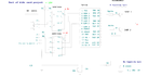
I want to know , for using MC33035 top drive output , best choice from Choice A or Choice B?
About , now MC33035 Bottom drive outputs , I made ohm's law and found these results:
R1 = 1150 Ohm HCPL led: Vf =1,5 V
R2 = 50 Ohm If = 10 mA
I added 1N4148 to be lower than 250 µA for Low level .
( With diode voltage drop about 1V )
Is schematic " Choice C " a good idea, or not needed to add 1N4148?
If only R = 1500 Ohm.
( 2-1,5) 1500 = 333 µA
Other question about HCPL2630 supply:
Mandatory to use a dc/dc converter or 7805 output will do the job ?
Thanks a lot.
jm
I have some queries about resistor values, if someone could reply it would be great....
In fact, i need to drive an IR2130 with optocoupler outputs.
Data for HCPL2630:
If maxi = 15 mA High level
If maxi = 250 µA Low level
Vf = 1,5 V
Data about MC33035:
Bottom drive output: ( pin 19 , 20 , 21 )
H: 12,9 13 V
L : 2V Maxi
I want to know , for using MC33035 top drive output , best choice from Choice A or Choice B?
About , now MC33035 Bottom drive outputs , I made ohm's law and found these results:
R1 = 1150 Ohm HCPL led: Vf =1,5 V
R2 = 50 Ohm If = 10 mA
I added 1N4148 to be lower than 250 µA for Low level .
( With diode voltage drop about 1V )
Is schematic " Choice C " a good idea, or not needed to add 1N4148?
If only R = 1500 Ohm.
( 2-1,5) 1500 = 333 µA
Other question about HCPL2630 supply:
Mandatory to use a dc/dc converter or 7805 output will do the job ?
Thanks a lot.
jm