Continue to Site

Welcome to EDAboard.com

Welcome to our site! EDAboard.com is an international Electronics Discussion Forum focused on EDA software, circuits, schematics, books, theory, papers, asic, pld, 8051, DSP, Network, RF, Analog Design, PCB, Service Manuals... and a whole lot more! To participate you need to register. Registration is free. Click here to register now.

Strange phase response of a LPF

Status
Not open for further replies.

milvapp

Member level 5
Joined
Apr 17, 2010
Messages
88
Helped
3
Reputation
6
Reaction score
2
Trophy points
1,288
Location
chania greece
Activity points
1,882
Hi,

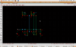
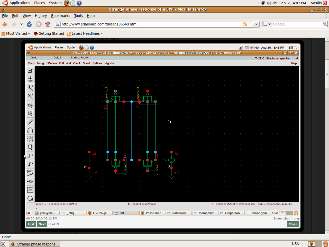
I am trying to implement a first order RC LPF with fc=500KHz
but instead of a regular R I use cascaded pmos working in cutoff region.
(image1)
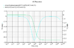
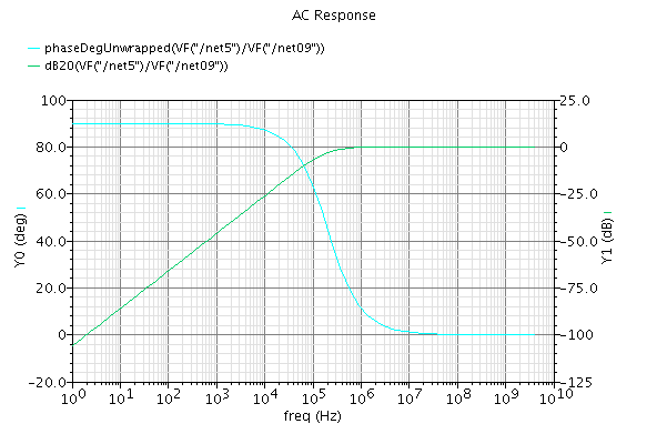
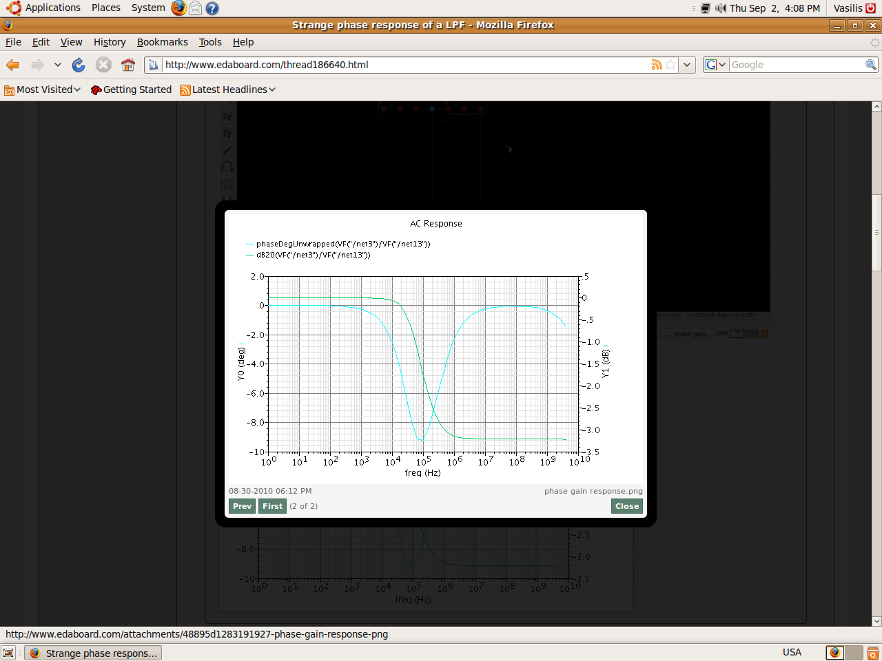
I did AC analysis and as you can see the gain graph goes as expected,compared to the
phase graph.Can someone explain to me why is this happening and how will it
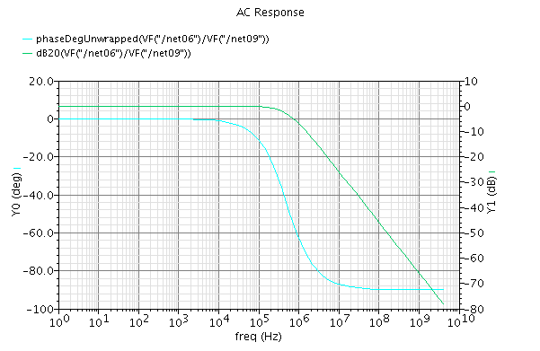
affect my filter?I have run AC analysis( substituting the cascaded pmos with a regular resistor) and the phase was fine.(At 45 deg f-3db was 500KHz).

These are the values of my circuit.
f=2.2GHz
fc=500KHz
R= 3.122MΩ
c=0,102 pF
W=120 um
L=200nm

Thnx in advance
 

Attachments

  • Screenshot-4.png
    Screenshot-4.png
    56.3 KB · Views: 136
  • phase gain response.png
    phase gain response.png
    6.9 KB · Views: 129

I worked out the gain and phase, all looks fine. Have you tried with a lump resistor instead of PMOS transistors?
 
Thank you for replying.

When you say,you worked out the gain and phase you mean with the pmos transistors?No I have to do it with the PMOS transistors...:(
 

I know you have do it with pmos, but to verify rerun your test with lumped resistor and see how is the ouput. Then we can cross verify where the problem is.
I calculated the gain with values you gave. f=2.2GHz
fc=500KHz
R= 3.122MΩ
c=0,102 pF what is this? 0,102 means here?
 
As i said at the first post I replaced the pmos with a lumped resistor and it works fine.Here you can see the results.
Though the 1.6 MΩ resistor takes a lot of space and thats why i have to do it with pmos.
I wrote c=0,102 pF for more accuracy,c=0,1 pF is the same.
 

can you please post the schematic again. It is not found.
 
there seem to be some problem. so pls post it again.
Its is coming as 404 Not Found nginx/0.6.32
 
milvapp: Check your pictures on first post again. I cannot see those pictures, seems like a dead link to mee. Maybe you should try uploading again.
 
I uploaded again the images.


---------- Post added at 01:48 PM ---------- Previous post was at 01:37 PM ----------

Yes you are right.By mistake I uploaded the phase-gain of a HPF.
I just uploaded the phase gain of the respective LPF with Lumped resistor.


Status
Not open for further replies.

Part and Inventory Search

Welcome to EDABoard.com

Sponsor

Back
Top