Continue to Site

Welcome to EDAboard.com

Welcome to our site! EDAboard.com is an international Electronics Discussion Forum focused on EDA software, circuits, schematics, books, theory, papers, asic, pld, 8051, DSP, Network, RF, Analog Design, PCB, Service Manuals... and a whole lot more! To participate you need to register. Registration is free. Click here to register now.

Need help on stepper motor controller using 89c51

Status
Not open for further replies.

almasee

Junior Member level 1
Joined
Feb 2, 2010
Messages
15
Helped
1
Reputation
2
Reaction score
1
Trophy points
1,283
Location
oman
Activity points
1,386
i want it in C++,please

hi,
good evening
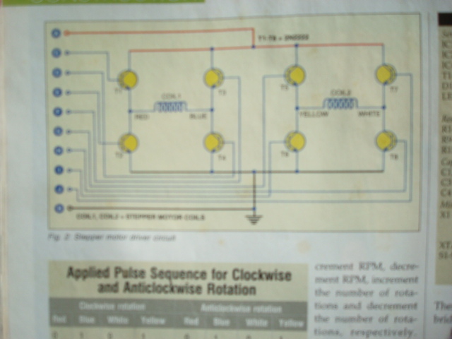
i have a project about stepper motor controlled by micro controller (89c51)
till know , we couldn't burn the programs because the language of program is assembly language(as they told us),so we you want you to give us an program with C++ or machine language
our machine should run at
1- run clock wise
2-run anticlockwise
3-increase /decrease RPM
4-increase /decrease revolutions
5-stop motor
6-change the mode
i hope you help us
my regards
info about contoller AT89C51.
 

i have same project with source basic code

Added after 1 minutes:

if you need i can post here
 
  • Like
Reactions: hirday

    hirday

    Points: 2
    Helpful Answer Positive Rating
yes please post them
 
  • Like
Reactions: hirday

    hirday

    Points: 2
    Helpful Answer Positive Rating
i have lost cd attached with mag i have to type whole code again may be tomorrow i can post here with hex code bye

Added after 5 minutes:

will this circuit suitable for you guys
 
In this Stepper motor control ..

ADC is connected to 8051 and variable voltage is INPUT to the ADC ..
ADC outupt of ADC is used to control the speed of the Stepper motor..


hope u get the ckt if u understand the program
#include<reg52.h>
#include<lcd.h>
#define ADCDATA P3

sbit INTR=P1^4;

void Step_Delay();

void main()
{
unsigned char i,j,Step[8]={0x01,0x02,0x04,0x08};
unsigned char Prev,Present,Adc_Value;
Prev=Present=0x00;
P2=0x0FF;
while(1)
{
INTR=0;
Delay_Us(40);
INTR=1;
Adc_Value=ADCDATA;
Prev=Present;
Present=Adc_Value;

if(Prev<Present)
for(j=0;j<50;j++)
for(i=0;i<8;i++)
{
P1=Step;
Step_Delay();
}
else
for(j=0;j<50;j++)
for(i=0;i<8;i++)
{
P1=Step[7-i];
Step_Delay();
}
}
}
void Step_Delay()
{
unsigned char i,j;
for(i=0;i<25;i++)
for(j=0;j<135;j++);
}
 
hiiiiiii mr. sant
can down load the picture again
to see it a whole
and the codes please
 

circuit is available here

**broken link removed**

---------- Post added at 13:59 ---------- Previous post was at 13:57 ----------

The Stepper motor need to pulse low at the data pin (i used the stepper that used 4 pin data). and the Vcc have two pins. the procedure is like this...

1. to move right or left just follow the direction of the data pins
example :
to move right :

data1-----data2-----data3----data4
0 --------- 1 -------- 1 -------- 1----->(15 degree)
1 --------- 0 -------- 1 -------- 1----->(30 degree)
1 --------- 1 -------- 0 -------- 1----->(45 degree)


to move left:

data1-----data2-----data3----data4
1 --------- 1 --------- 1 ------- 0----->(15 degree)
1 --------- 1 --------- 0 ------- 1----->(30 degree)
1 --------- 0 --------- 1 ------- 1----->(45 degree)

and so on...

using assembly language, here some example

mov p1,#0ffh ; set the default value to 1

clr p1.0 ; 15 degree move to left

mov a, p1

rl a

mov p1,a ;move again 15 degree left

rl a

mov p1, a ; move again 15 degree left
 
  • Like
Reactions: almasee

    V

    Points: 2
    Helpful Answer Positive Rating

    almasee

    Points: 2
    Helpful Answer Positive Rating
thanks for you help
but one master told me ,if you want to burn programme inside the microcntroller
you have to write programme in hexfile (i think).
the problem now how i can write programme because unluky or Dr and Mr and Ms. they dont know
so you advice sir
 

Code:
:10000000752a32752b01752c05752d01c22fc22e54
:1000100078017590ffe590b4ff020115c28013507e
:10002000030880fa310ed280b8010411698030b81b
:10003000020411868029b80309302f02d28311a34c
:10004000801db80409302f02d28311bd8011b8057c
:1000500009302e02d28411d78005b8060211e87546
:10006000a0ff7590ff780180acab2cc28175a033e6
:10007000310275a03c3102d28175a0cc310275a04d
:10008000c33102dbe622ab2cc28275a0333102758c
:10009000a0c33102d28275a0cc310275a03c3102de
:1000a000dbe622c283ac2bbc0a04d22f01bc052b99
:1000b000852bf0743284f52a310ed28322c283acb0
:1000c0002bbc0104d22f01d6152b852bf074328462
:1000d000f52a310ed28322c284052d7405852df0b8
:1000e000a4f52c310ed28422c284ac2dbc0104d2e2
:1000f0002e2101152d7405852df0a4f52c310ed27d
:100100008422a92a7ac8000000dafbd9f7227efff0
:0c0110007fc8000000dffb0000def522cd
:00000001ff
you can burn this hex file to the chip
here is the source code

Code:
 uf1 equ 2fh
        uf2 equ 2eh
        org 0000h               
           mov 2ah,#32h
           mov 2bh,#01h
           mov 2ch,#05h
           mov 2dh,#01h
           clr uf1
           clr uf2
           mov r0,#01h
           mov p1,#0ffh           
    lop:   mov a,p1
           cjne a,#0ffh,jump
           ajmp lop

  jump:     clr p0.0
  loop:    rrc a    
           jnc num
           inc r0
           sjmp loop
      num: acall dely
           setb p0.0
           
           cjne r0,#01h,nxt           
           acall clkwise
           sjmp over
    nxt:   cjne r0,#02h,nxt2      
           acall aclkwise
           sjmp over
   nxt2:   cjne r0,#03h,nxt3
           jnb uf1,ledoff
           setb p0.3
   ledoff: acall incrpm
           sjmp over
   nxt3:   cjne r0,#04h,nxt4
           jnb uf1,ledof
           setb p0.3
   ledof:  acall decrpm
           sjmp over
   nxt4:   cjne r0,#05h,nxt5
           jnb uf2,of
           setb p0.4
   of:     acall incnum
           sjmp over  
   nxt5:   cjne r0,#06h,over          
           acall decnum
         
   over:   mov p2,#0ffh
           mov p1,#0ffh
           mov r0,#01h
           sjmp lop          

   clkwise:         
         mov r3,2ch
   rot:  clr p0.1
         mov p2,#33h
         acall delay
         mov p2,#3ch
         acall delay
         setb p0.1
         mov p2,#0cch
         acall delay
         mov p2,#0c3h
         acall delay         
         djnz r3,rot
         ret

   aclkwise:         
         mov r3,2ch
  rott:  clr p0.2
         mov p2,#33h
         acall delay
         mov p2,#0c3h
         acall delay
         setb p0.2
         mov p2,#0cch
         acall delay
         mov p2,#3ch
         acall delay         
         djnz r3,rott
         ret

      incrpm:
         clr p0.3
         mov r4,2bh
         cjne r4,#0ah,incr
         setb uf1
         ajmp out
  incr:  inc 2bh
         mov b,2bh
         mov a,#32h
         div ab
         mov 2ah,a
         acall dely
         setb p0.3
   out:  ret
   
     decrpm:
         clr p0.3
         mov r4,2bh
         cjne r4,#01h,decr
         setb uf1
         ajmp out1
  decr:  dec 2bh
         mov b,2bh
         mov a,#32h
         div ab
         mov 2ah,a
         acall dely
         setb p0.3
   out1: ret

     incnum:
         clr p0.4
         inc 2dh
         mov a,#05h
         mov b,2dh
         mul ab
         mov 2ch,a
         acall dely
         setb p0.4
         ret
      decnum:
         clr p0.4
         mov r4,2dh
         cjne r4,#01h,decn
         setb uf2
         ajmp out2
   decn: dec 2dh
         mov a,#05h
         mov b,2dh
         mul ab
         mov 2ch,a
         acall dely
         setb p0.4
   out2: ret

    delay:
         mov r1,2ah
    lp5: mov r2,#0c8h
    lp4: nop
         nop
         nop
         djnz r2,lp4
         djnz r1,lp5
         ret

     dely:        
         mov r6,#0ffh
    lp2: mov r7,#0c8h
    lp1: nop
         nop
         nop
         djnz r7,lp1
         nop
         nop       
         djnz r6,lp2         
         ret

       end


---------- Post added at 02:00 ---------- Previous post was at 01:58 ----------

you can use above circuit diagram
 

    V

    Points: 2
    Helpful Answer Positive Rating
really i dont know how to thank you
i will show the information to my teaachers ,i wish they meet our need
thanks from my heart to you all
 

what is the working principle of project
function of each part
the terminal from j to c for stepper motor ,am i right
A & b what is the use of them
 

what is the working principle of project
function of each part
the terminal from j to c for stepper motor ,am i right
A & b what is the use of them
please expand properly what you are going to say here,
what are those J & C?
 

what is the working principle of project
function of each part
the terminal from j to c for stepper motor ,am i right
A & b what is the use of them
the circuit that is above is incomplete i'll post may be tomorrow i have to search old magazine pls wait ok
 

also i want data sheet of drive circuit and and specifications of the stepper motor because i already bought one...


thanks for ur help
 

this might help you

---------- Post added at 03:59 ---------- Previous post was at 03:47 ----------

pls check the terminals again
from up
A
C
D
E
F
G
H
I
J
B
 
specifications of our stepper motor
max rating voltage 5 v
max rated current per coil 0.5 amp
max rpm 20 for single and double coil excitation/ 60 in half step
torque 1.5 kg per cm2
step resolution 1,8 degree per pulse

but your stepper motor specification that you upload it

---------- Post added at 08:15 ---------- Previous post was at 08:14 ----------

specifications of our stepper motor
max rating voltage 5 v
max rated current per coil 0.5 amp
max rpm 20 for single and double coil excitation/ 60 in half step
torque 1.5 kg per cm2
step resolution 1,8 degree per pulse

but your stepper motor specification that you upload it
 

Status
Not open for further replies.

Part and Inventory Search

Welcome to EDABoard.com

Sponsor

Back
Top