Continue to Site

Welcome to EDAboard.com

Welcome to our site! EDAboard.com is an international Electronics Discussion Forum focused on EDA software, circuits, schematics, books, theory, papers, asic, pld, 8051, DSP, Network, RF, Analog Design, PCB, Service Manuals... and a whole lot more! To participate you need to register. Registration is free. Click here to register now.

Problem with the curvature of a bandgap from Razavi's book

Status
Not open for further replies.

Usman Hai

Full Member level 3
Joined
Apr 8, 2004
Messages
158
Helped
12
Reputation
24
Reaction score
9
Trophy points
1,298
Location
Canada
Activity points
1,230
Hi, I am simulating the bandgap given in Razavi book as shown in figure. I am using TSMC 0.18um tech.
66_1175702663.jpg


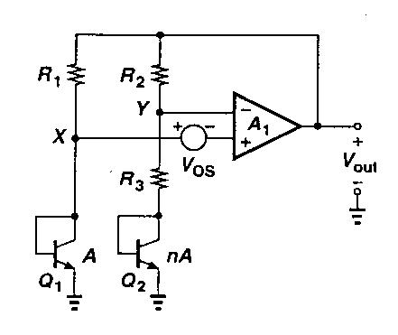
The problem is I am not getting the curvature as indicated in the book and othr books. I am getting linear downward slope, yes of less than 1mV, but I need the curvature when sweeping the temperature from 0C till 100C. Is it because of 0.18um tech or what?
Can you tell me what device sizes I should use for Bipolar areas and what should be the temperature coefficients of real resistors on chip. Any suggestion or hint will be extremely useful.
I heard also that it might be simulator error, but I need to confirm so any opinion on this will be highly appreciated as well.
Thanks in advance[/img]
 

Re: bandgap question

Two steps for you to do:

1) In you bandgap circuit, zero TC point is negative temperature. Try to sweep your tempareture range from -100C to 100C, you may the desired curve. I think this is mainly because your opamp offset voltage and resistor ratio (R3+R2)/R3 shift the curver to left.

2) Since you are getting downward slope which means negative TC, what you should do is to increase the resistor ratio (R3+R2)/R3 to move zero TC point to your desired tempareture.

When you really fabricate a bandgap, you need to add more dummy resistors and resistor taps in your layout for future trimming and metal mask change.
 

    Usman Hai

    Points: 2
    Helpful Answer Positive Rating
Re: bandgap question

You have your Zero TC point in a negative temperature, you have to move it to a positive temperature.

It's more important to choose the ratio between the two areas than the area of each bjt, because you could achieve a better matching. For achieving a better matching use COMMON-CENTROID LAYOUT. The ratio could be 8, 24, 48, etc.

The temperature coefficients of real resistors on chip depend of the resistors material, I suggest you use high-resistive polysilicon (1.2kohm/square), TC=-0.0004/K
 

    Usman Hai

    Points: 2
    Helpful Answer Positive Rating
Status
Not open for further replies.

Part and Inventory Search

Welcome to EDABoard.com

Sponsor

Back
Top