Continue to Site

Welcome to EDAboard.com

Welcome to our site! EDAboard.com is an international Electronics Discussion Forum focused on EDA software, circuits, schematics, books, theory, papers, asic, pld, 8051, DSP, Network, RF, Analog Design, PCB, Service Manuals... and a whole lot more! To participate you need to register. Registration is free. Click here to register now.

DAC Layout

Status
Not open for further replies.

Ans5671

Member level 2
Joined
Jan 7, 2021
Messages
45
Helped
0
Reputation
0
Reaction score
5
Trophy points
8
Activity points
259
Hello all,
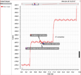
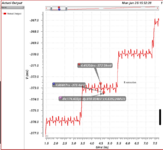
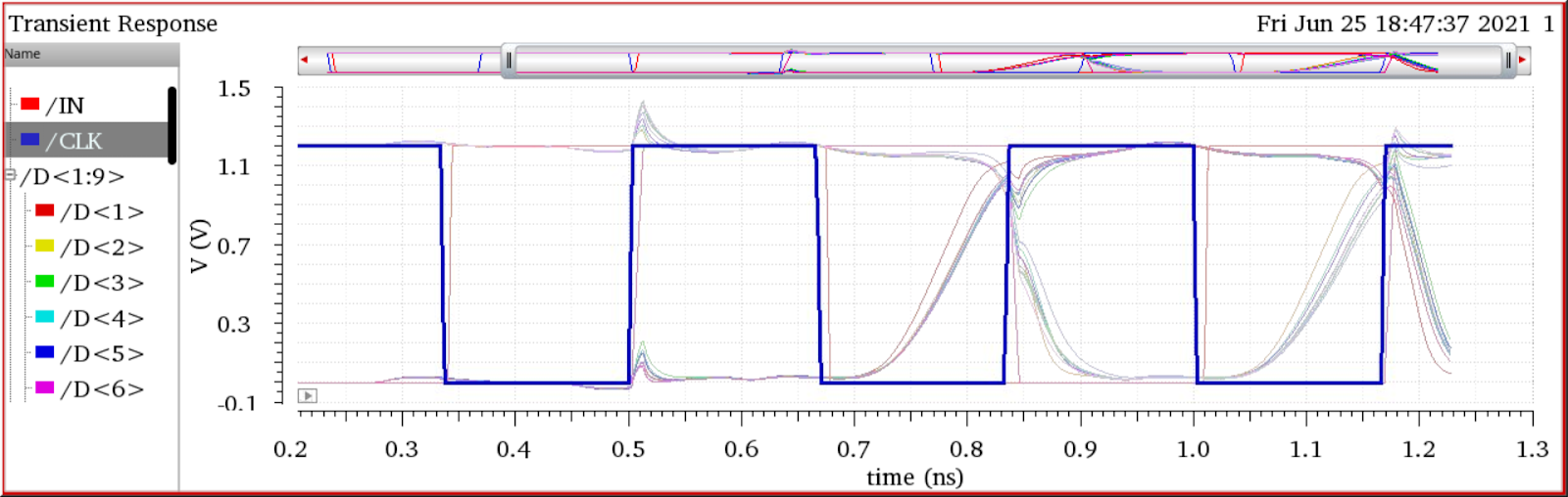
I am designing a 9 bit binary-weighted Nyquist DAC @3GHz. The schematics are ready with good results. I started the layout of the different blocks as Current Source Matrix, Current switches, Current switch drivers. I am not getting good results, mainly because of clock coupling to the driving signals. The clock is routed at M7 and signals on M2 and M3. Can someone help me - I have tried two different floor plans for the switch drivers. Clock - H tree and Mesh.
TMADmSklINpeOes_yZCBtRW0SpCieJG7iYLoJBDzJle8kQAEvJHR_DxHNm10xT3N5OD0M3II8sDx4VP1ye8IQiuu8AR_xE3uUxtifONmMdwdKeni0-_rrQEsjkTCMlT0I-c7jc58ilE
 

Hey,
M7 to M3 is pretty far, you can try enhance the layout with shielding the clock's routing with bottom vssa plate(and even side&top shield). I would also see what happens with r-only extraction to examine if it cc issue.
 

    Ans5671

    Points: 2
    Helpful Answer Positive Rating
There will always be the G-D coupling of clocks into analog
nodes. Hard switching is worst. Current-steering can be a lot
lower clock-noise input-output bleed-over. But at 3GHz you
may need all the gate drive you can get. Question is where
reducing gate drive stops reducing settling time, or adds
some other error (like, switch no longer looks like a switch
but more of a resistor with variabilities).

A current source DAC where the "switch" is a diff pair that
steers current away or to the summing node, the gate on
the "to" side is static and the control side only swings just
enough to fully steer current, may be the least clock noise
injection.
 

    Ans5671

    Points: 2
    Helpful Answer Positive Rating
I agree with the comments above. It could be worth extracting the parts individually, perhaps it's not the "long" clock routing that is an issue but inside the current cell itself. This also gives smaller netlists that are easier to dechiper to find the actual problem.
 

I agree with the comments above. It could be worth extracting the parts individually, perhaps it's not the "long" clock routing that is an issue but inside the current cell itself. This also gives smaller netlists that are easier to dechiper to find the actual problem.
It would certainly be instructive to check how much of the
"noise" is present in ideal unit cells or the whole assembly
without parasitics (aside from those embedded in the FET
compact model) so that you understand the relative
contributions of the various "candidates".
 

Thank you. for the replies.

@guntherleet
I have added GND shielding on M5/M6. With that, the disturbances on the output reduced from 3mV to 250uV. I do not understand why there are disturbances (~900uV) in the R only extraction? It is also greater than in CC extraction (250uV). Is it the gate to drain coupling that @dick_freebird is talking about? But this disturbance is not observed in the No RC extraction.

@dick_freebird I have used an inverter chain of 3 inverters to reduce the clock coupling to the signals - At the schematic level - no coupling can be seen.
Can you please clarify this - "the gate on the "to" side is static and the control side only swings just enough to fully steer current maybe the least clock noise injection." In a fully differential both the gates turn on/off in the opposite polarity - hence not static. Isn't it?

Also, How to check this - "how much of the "noise" is present in ideal unit cells or the whole assembly without parasitics (aside from those embedded in the FET compact model) so that you understand the relative contributions of the various "candidates"."
 

Attachments

  • Screenshot from 2021-06-28 16-31-06.png
    Screenshot from 2021-06-28 16-31-06.png
    92.1 KB · Views: 135
  • Screenshot from 2021-06-28 16-31-19.png
    Screenshot from 2021-06-28 16-31-19.png
    77.5 KB · Views: 124
Last edited:

Status
Not open for further replies.

Part and Inventory Search

Welcome to EDABoard.com

Sponsor

Back
Top