papaisou11
Member level 2
Hi...
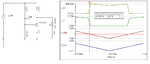
I am designed a boost regulator using switching regulator topology from webench design tool by TI.
IC name is LM3478
The circuit specifications are as follows:-
1. Vin :- 6.4v to 7.4v.
2. Vout:- 9v 1.5A
3. Expected efficiency by the report from webench is more than 90%.
I am using a battery Lithium ion 7.4v with 2000mAH capacity. I just want to make an 9V/1.5A backup for 5-10 minutes.
My question is how to implement a led which will glow when battery output is low. I have seen that 5v boost converter use LBI/LBO pins for achieving this state. But how to implement in my circuit?
Also, I have seen fuel gauge ic's, all are very expensive, Is there any way in low cost implementation? I want analog, just light up one led below threshold value.
Can I use a comparator and differentiate two input values and light up a led at the output? But if I do will it be near accurate in load? what about the hysteresis?
Thanks and Regards,
SaV