Continue to Site

Welcome to EDAboard.com

Welcome to our site! EDAboard.com is an international Electronics Discussion Forum focused on EDA software, circuits, schematics, books, theory, papers, asic, pld, 8051, DSP, Network, RF, Analog Design, PCB, Service Manuals... and a whole lot more! To participate you need to register. Registration is free. Click here to register now.

[PIC] Three Phase AC Induction Motor Constant V/F Drive Help Needed

Status
Not open for further replies.

Okada

Banned
Joined
Jun 16, 2016
Messages
1,159
Helped
129
Reputation
252
Reaction score
129
Trophy points
63
Activity points
0
I need to build Three Phase AC Induction Motor Constant V/F Drive using PIC18F. I want to know

1. Do I need 3x Full-Bridge outputs for driving the AC Induction Motor ?
2. To maintain constant V/F do I need 3 phase feedback voltages or can one feedback sufficient ?

- - - Updated - - -

I am really sorry. The previous post time is not expiring. The same post got updated after 45 minutes.

3. Can't I use 3x Full-Bridge to drive 3 load ? Will I have problem connecting the load ?
4. Should I use 3x Half-Bridge for the three phase load ?

- - - Updated - - -

Referring to power electronics books and articles I found that 3x Half-Bridges are used for AC Indcution Motor control.
I generated3x Half-Bridge SPWMs

I generated the following signals

P1A, P1B
P2A, P2B
P3A, P3B

In Half-Bridge mode I can't change the direction of the PWM.

Both PxA and PxB are modulated but complementary to each other.

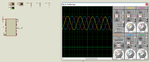
Please check the attached video and tell me if the signals are correct.

There is 120 degree phase shift between each signal pair.

I want to know how to connect RC filter to PxA and PxB to check if proper sinewave is obtained or not.

I am also attaching Proteus file and .hex file if anybody wants to simulate and check the signals.

There is a small issue with the code. I am using 8 MHz crystal with 4x PLL = 32 MHz clock and code inside ISR needs 90us to execute but ISR is called once every 78us. I think I need to reduce the PWM frequency. Currently I am using 12 KHz PWM frequency. I will fix the code and post it soon.


To maintain constant V/F ration with feedbacking phase voltage I have to change the frequency but I want to know should feedback all the three phase scaled voltages and use three variables for frequency and control the frequencies of each phase separately or should I feedback just one scaled and rectified phase voltage to adc and use one variable for controlling the frequency of all the three phases.
 

Attachments

  • Three Phase AC Induction Motor Constant V-F Drive.rar
    225.6 KB · Views: 168

Hi,

Looking at a single design (for driving three phase motor) answers a lot of your questions.

Indeed I recommend not to reinvent the wheel.
Many IC manufacturers have complete documentatiin on how to do this.
They have reference designs.

..and every design begins with specifications.
Input voltage, output voltage, output frequency, load active power, continous load current, start up motor current...and everything ekse that is important for your design.

Then - with the help of those informations - find out what circuit to use.

Klaus

- - - Updated - - -

Hi,

What is "direction of PWM"?

Klaus
 

@KlausST

Ok. I will search and read the documents.

For now I have a question.

In PIC18F87K22 datasheet page no. 268, section 20.4.1 it says the PxA nd PxB are complementary but why I am not getting complementary signals ?

This is my PWM Initialization code. I am using mikroC PRO PIC.


Code C - [expand]
1
2
3
4
5
6
7
8
9
10
11
12
13
14
15
16
17
18
19
20
21
22
23
24
25
26
27
28
29
30
31
32
33
34
35
36
37
38
39
40
41
42
43
44
45
46
PWM1_Init(12821);
     PWM1_Set_Duty(0);
 
     CCP1CON.CCP1M3 = 1;
     CCP1CON.CCP1M2 = 1;
     CCP1CON.CCP1M1 = 1;
     CCP1CON.CCP1M0 = 0;
              
     CCP1CON.P1M0 = 0;
     CCP1CON.P1M1 = 1;
     
     
     PWM2_Init(12821);
     PWM2_Set_Duty(0);
 
     CCP2CON.CCP2M3 = 1;
     CCP2CON.CCP2M2 = 1;
     CCP2CON.CCP2M1 = 1;
     CCP2CON.CCP2M0 = 0;
              
     CCP2CON.P2M0 = 0;
     CCP2CON.P2M1 = 1;
          
     
     PWM3_Init(12821);
     PWM3_Set_Duty(0);
 
     CCP3CON.CCP3M3 = 1;
     CCP3CON.CCP3M2 = 1;
     CCP3CON.CCP3M1 = 1;
     CCP3CON.CCP3M0 = 0;
              
     CCP3CON.P3M0 = 0;
     CCP3CON.P3M1 = 1;
     
     Delay_ms(200);
              
     InitTimer2();
         
     TRISC = 0x00;
     TRISE = 0x00;
     TRISG = 0x00;
     
     PWM1_Start();
     PWM2_Start();   
     PWM3_Start();


Edit:

Got the correct Half-Bridge Signals. Now PxA and PxB are complementary. Here is the changes.


Code C - [expand]
1
2
3
4
5
6
7
CCPxCON.CCPxM3 = 1;
CCPxCON.CCPxM2 = 1;
CCPxCON.CCPxM1 = 0;
CCPxCON.CCPxM0 = 0;
 
CCPxCON.PxM0 = 0;
CCPxCON.PxM1 = 1;

 
Last edited:

Here is the picture which shows the 3 Phase AC signals. See the attached video. It shows how the Half-Bridge SPWM signals should be. In the videos posted in post #1 and #4 the signals from top are P1A, P1B, P2A, P2B, P3A and P3B.

Always test with low voltage (5V/3.3V) signals without connecting the VBUS voltage to the mosfets or test with Proteus. If your Half-Bridge SPWM signals look like the ones shown in video of post #1 then please don't connect VBUS voltage to mosfets, otherwise the VBUS voltage with short to ground because the PxA nd PxB signals are not complementary and they will turn ON both the high-side and low-side Mosfets at the same time.

If your Three Phase Half-Bridge signals look like the ones shown in video of this post then you can safely connect VBUS voltage to Mosfets. The PxA nd PxB (eg; P1A and P1B) signals are complementary and only either high-side or low-side Mosfet will be On at a time.

I am attaching Proteus simulation if anybody want to see the signals.

One has to use IR2112 or similar FET driver which has two inputs and whose outputs are in phase with inputs becuase there are two complementary signals like P1A and P1B.

Another simpler method I guess is to generate 3x SPWM signals which are 120 degrees apart from each other and input each signal to one IR2184 which has one input and which gives two outputs. The IR2184 converts one signal to two complementary signals for driving High-side and low-side switches.

I still have not received any answer for the question I asked in post #1 that is do I need to feedback only one phase to control the frequency of all the three phases or do I have to feedback all the three phases (scaled and rectified) and contrl the frequency of each phase separately.
 

Attachments

  • Three Phase AC Induction Motor Constant V-F Drive RevB.rar
    311.8 KB · Views: 101
  • Three Phase Signals.png
    Three Phase Signals.png
    98.9 KB · Views: 168

I still have not received any answer for the question I asked in post #1
Well, the question asks for a decision between two alternatives, but the first is wrong and the second technically impossible.

"Constant V/f" actually means that the voltage is varied according to motor frequency, not the other way around. And the simple fact that the three phases have fixed 120° phase shift involves that they must be driven with the same frequency.

There are VFD drives that reduce the frequency in case of overload, but that's a different topic. I'm not aware of a VFD drive implementing "voltage feedback", instead there's an inverse feed-forward from bus voltage to duty cycle to keep the output voltage constant.

I notice that you finally managed complementary waveforms in the latest simulation, but the duty cycle doesn't seem to cover the 0 to 100 % range, as required for full output voltage.
 
  • Like
Reactions: Okada

    Okada

    Points: 2
    Helpful Answer Positive Rating
@FvM

Thank you for explaining clearly. I was waiting for the replies and particularly for the feedback thing. Now I will feedback one phase voltage scaled and rectified to adc input and control the voltage of all the phases.

I will use same method as mentioned in the AC > DC > AC converter thread where I modified and used Thamid's feedback method.

Even I saw the signals on the proteus simulation and had doubt which you mentioned. I am using 12.1 KHz PWM and using ECCP and 9-bit PWM duties.

Max 9-bit value is 512 but I have taken only 98% of 512 for the max pwm duty in the sine table but still as you mentioned even I suspect that PWM duties are not going to 98% or 100%. I am trying to find out what is causing that.

Also I have one more problem and still trying to find solution for it. You can see in the 3 Phase sinewve that the 3rd phase voltage (pink signal) is distorted at 0 degrees.
 
Last edited:

I assume its caused by your code.

Yes, even I think like that. I modified Thamid's SPWM generation for 3 Phase SPWM.

https://tahmidmc.blogspot.in/2012/10/generation-of-sine-wave-using-spwm-in_10.html

I will post code if anybody need to see.

One problem there is that ISR is called once every 78 us (78.1 KHz PWM) and ISR code takes 90 us to execute. maybe that is causing the distortion in third phase signal as code of 3rd phase signal is at the end of ISR.

First I will change to PWM frequency to 10 KHz as client requested for it and then I will get 100 us Interrupt. So, code inside ISR will have time to execute.

I will try this and for this I have to make the calculations again. After trying this I will post the code.
 

Hi,

I will post code if anybody need to see.
;-)

I´d say it´s fairly impossible to verify your code without seeing it.

****
ISR is called once every 78 us (78.1 KHz PWM) and ISR code takes 90 us to execute
The invention of the time warp...


Klaus
 

I am trying. OSCCON was not properly configured. I configured it properly and now ISR code takes 80 us to execute and I changed PWM frequency to 10 KHz and Timer 2 Interrupt to 100 us. Still distorted signal problem is not solved. I will try once more and if I don't succeed then I will post code. Client had asked not to post code.

- - - Updated - - -

I am using two different methods for generating Push-Pull signals namely.

1. PxA and PxB half-Bridge signals and using IR2112

2. Using PWM Mode and with IR2184.

In both methods I was getting distortion in 3rd Phase Sinewave at 0 degrees. The problem was in code.

This was the original code.


Code C - [expand]
1
2
if((DUTY_CYCLE[2] + 20) < 64)DUTY_CYCLE[2] += 20;
else DUTY_CYCLE[2] -= 42;


I changed it to


Code C - [expand]
1
2
if((DUTY_CYCLE[2] + 21) < 64)DUTY_CYCLE[2] += 21;
else DUTY_CYCLE[2] -= 43;


and now there is no distortion.

Also I got the IR2184 working in Proteus. I had to connect VS pin to GND. Proteus simulation attached. I have also attached simulation video for those who don't have Proteus. It shows 3-Phase SPWM, 3-Phase Sinewaves and CCP3 + HO + LO signals. You can see that the voltage level of HO and LO signals are 11V to drive the Mosfets gate. The vertical grid in oscilloscope of Proteus is 5V.

Here is the code of SPWM generation. The problem which FvM mentioned which is duty not reaching 100% is not yet solved. Please somebody check the code and point out the problem.


Code C - [expand]
1
2
3
4
5
6
7
8
9
10
11
12
13
14
15
16
17
18
19
20
21
22
23
24
25
26
27
28
29
30
31
32
33
34
35
36
37
38
39
40
41
42
43
44
45
46
47
void interrupt() {     
     if((TMR2IE_bit) && (TMR2IF_bit)) { 
        //Enter your code here
        
        //SET_FREQ = 65536 / (64 * 2) = 256
        //Required AC Frequency = 50 Hz
        //PWM Freq = 10 KHz
        //Tpwm = 1/10 KHz = 100 us  (Timer2 Interrupt Period)
        //100 us * 64 * 2 = 12.8 ms (for 180 degrees)
        //12.8 * 2 = 25.6 ms
        //AC freq = 1/25.6 ms = 39 Hz      
                
        TBL_POINTER_NEW[0] = TBL_POINTER_OLD[0] + SET_FREQ;
        TBL_POINTER_SHIFT[0] = TBL_POINTER_NEW[0] >> 10;
        DUTY_CYCLE[0] = TBL_POINTER_SHIFT[0];        
        //Assign PWM duty 10 bit     
        CCPR3L = (sine_table[DUTY_CYCLE[0]] & 0x3FC) >> 2;
        CCP3CON.DC3B1 = (sine_table[DUTY_CYCLE[0]] & 0x02) >> 1;
        CCP3CON.DC3B0 = (sine_table[DUTY_CYCLE[0]] & 0x01);        
        TBL_POINTER_OLD[0] = TBL_POINTER_NEW[0];


        TBL_POINTER_NEW[1] = TBL_POINTER_OLD[1] + SET_FREQ;
        TBL_POINTER_SHIFT[1] = TBL_POINTER_NEW[1] >> 10;
        DUTY_CYCLE[1] = TBL_POINTER_SHIFT[1];        
        if((DUTY_CYCLE[1] + 42) < 64)DUTY_CYCLE[1] += 42;
        else DUTY_CYCLE[1] -= 22;        
        CCPR4L = (sine_table[DUTY_CYCLE[1]] & 0x3FC) >> 2;
        CCP4CON.DC4B1 = (sine_table[DUTY_CYCLE[1]] & 0x02) >> 1;
        CCP4CON.DC4B0 = (sine_table[DUTY_CYCLE[1]] & 0x01);        
        TBL_POINTER_OLD[1] = TBL_POINTER_NEW[1];
           
        TBL_POINTER_NEW[2] = TBL_POINTER_OLD[2] + SET_FREQ;
        TBL_POINTER_SHIFT[2] = TBL_POINTER_NEW[2] >> 10;
        DUTY_CYCLE[2] = TBL_POINTER_SHIFT[2];        
        if((DUTY_CYCLE[2] + 21) < 64)DUTY_CYCLE[2] += 21;
        else DUTY_CYCLE[2] -= 43;        
        //Assign PWM duty 10 bit        
        CCPR5L = (sine_table[DUTY_CYCLE[2]] & 0x3FC) >> 2;
        CCP5CON.DC5B1 = (sine_table[DUTY_CYCLE[2]] & 0x02) >> 1;
        CCP5CON.DC5B0 = (sine_table[DUTY_CYCLE[2]] & 0x01);        
        TBL_POINTER_OLD[2] = TBL_POINTER_NEW[2];  
            
        TMR2IF_bit = 0;        
     }    
}


Attachments

  • PWM Mode.rar
    651.4 KB · Views: 127

Got it working. According to my PR2 value my pwm resolution was 9.6 bit = 776. 98% of 776 is 761.


Code C - [expand]
1
2
3
4
5
6
7
8
9
10
const code unsigned int sine_table[64] = {
    0,2,7,16,29,45,64,86,
    111,139,169,201,235,270,306,343,
    381,418,455,491,526,560,592,622,
    650,675,697,716,732,745,754,759,
    761,759,754,745,732,716,697,675,
    650,622,592,560,526,491,455,418,
    381,343,306,270,235,201,169,139,
    111,86,64,45,29,16,7,2                        
};


The questions asked in the previous posts has been solved but I am not closing the thread because I have two new questions related to to the same project.

IR2184 datasheet page no. 2 says

VB = VS + 11.3 (Vcc - 0.7)
VHO = VS to VB = 24V to 35.3V (in my case)
VLO = 0 to VCC = 0 to 12V

In Proteus I am getting LOAD1 signal (green signal) as 24V which is correct but why HO1 (blue) signal is not correct ?
The vertical grid for CCP3 (yellow) and LO1 (pink) signals are 5V and for HO1 (blue) and LOAD1 (yellow) signals it is 10V.

CCP3, LO1 and LOAD1 signals are correct but HO1 signal is not correct.

I am attaching latest Proteus circuit and .hex file for simulation. Also I am attaching simulation video for those who don't have Proteus.

It shows pwm duty varying between 0 and 98% which was mentioned in previous post.

Mods, if you feel video file is big then inform me and I will delete it and upload it to mediafire and post the link here. I uploaded it because it is < 1 MB.

Filters and some Oscilloscopes are excluded in the simulation.

1. Why HO1 signal is not correct ( not 35.3V )?

I am using PWM mode to generate SPWM. PIC18F46K22 datasheet says PWM direction can only be changed in Full-Bridge mode and not in PWM and Half-Bridge mode. My sine table is for 180 degrees

2. How am I getting sine wave ? Should not I get only helf sine wave ? Video in previous posts show three phase sine wave signals.


Edit:

I have also attached circuit in PDF format for those who don't have Proteus so that they can check the connections of signals to oscilloscopes.
 

Attachments

  • Three Phase ACIM Constant VF - PWM Mode.rar
    538.3 KB · Views: 144
  • Three Phase AC Induction Motor Constant V-F Drive - PWM Mode.PDF
    36 KB · Views: 96
Last edited:
@FvM

In Three Phase AC Induction Motor if load varies then V varies. So, I feed back voltage to PIC adc and monitor it and based on this adjust the PWM duty to get constant V for all possible loads ?
 

In Three Phase AC Induction Motor if load varies then V varies.

The external applied voltage does not change; if the load increases, the phase difference between the applied voltage and the current in the coil decreases.

In other words, the current and voltage comes closer (power factor increases) and the motor takes more power.
 
  • Like
Reactions: Okada

    Okada

    Points: 2
    Helpful Answer Positive Rating
To complement what C-Mitra mentions:

if he motor load increases, the rotor slip increases which has two effects:
-the speed decreases
-the torque increases.

That is the way induction motors work. See curve below:


[found at: machineryequipmentonline .com /electric -equipment /wp -content /uploads /2016 /01 /INDUCTION -MOTORS -ROTATING -FIELD -SLIP -AND -TORQUE -0580 .jpg ]

The peak of the torque curve is called breakdown torque. If that value is exceeded, the motor will stall.
 
Last edited by a moderator:
  • Like
Reactions: Okada

    Okada

    Points: 2
    Helpful Answer Positive Rating
What should I do to correct power factor ? Implement Active Power factor correction ?

@FvM

So, I have to read the frequency of one phase and then adjust the Phase Voltages by changing SPWM duty ?
 

@FvM

Can't I use IR2184 or IR2186 for Three phase ACIM Control Circuit ? Should I use TLP250 ? IR2184/6 max rating is 600V and VBUS is 560V DC.

If TLP250 is better, is it better to use TLP250 which is optically isolated or is it better to use IX2120 ?

https://www.mouser.in/new/ixys/ixys-ix2120-driver/
 
Last edited:

I got it. I have to read the motor speed (frequency) using tachometer and then adjust the voltage to maintain constant V/F ratio. Right ?
 

I got it. I have to read the motor speed (frequency) using tachometer and then adjust the voltage to maintain constant V/F ratio. Right ?

Not quite accurate; I admit it is messy but only a little.

You have three independent (well, some may not agree but that is a different story) variable; load, torque and speed. All of them can be changed "within reason and limits" independently.

But you can control only the frequency and applied voltage. The current adjusts itself to the load (see the graph in #15) and the speed can be regulated within the limits by changing the voltage.

Looking back, load, torque and speed are actually related and we can safely ignore load and consider torque and speed. Together they decide the power output at the motor shaft. In fact that is all that matters.

Look at the motor load curves and decide on a voltage and frequency consistent with the output power needed.

Changes in load will mean a change in output power; you will need to change the V and F depending on the graph to keep the output power. In general, there will more than one way to do that...
 
  • Like
Reactions: Okada

    Okada

    Points: 2
    Helpful Answer Positive Rating
In post #5 FvM mentioned that voltage is adjusted based on the motor frequency. Motor frequency depends upon load. So, I decided to read motor frequency per 100 ms and then adjust the voltage to maintain constant V/F ratio. I have been assigned the task of designing the Driver circuit and write code for MCU. I don't have the motor. After I write code and design hardware I will send the PCB to other country where it will be tested. They will connect the Driver to motor and run it without load. Then frequency and voltage is noted down. Based on this data I will make changes to the code to adjust voltage based on motor frequency.
 

Status
Not open for further replies.

Similar threads

Part and Inventory Search

Welcome to EDABoard.com

Sponsor

Back
Top