Continue to Site

Welcome to EDAboard.com

Welcome to our site! EDAboard.com is an international Electronics Discussion Forum focused on EDA software, circuits, schematics, books, theory, papers, asic, pld, 8051, DSP, Network, RF, Analog Design, PCB, Service Manuals... and a whole lot more! To participate you need to register. Registration is free. Click here to register now.

Ultra wide band power divider design problem

Status
Not open for further replies.

AmmarAli

Junior Member level 1
Joined
Mar 27, 2015
Messages
19
Helped
0
Reputation
0
Reaction score
0
Trophy points
1
Activity points
133
Hi
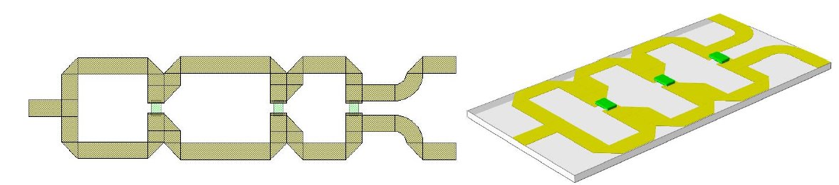
I'm working on designing an ultra wide band power divider (3.1-10.6GHz) , I've done a basic structure which is the first attachment then increased the angle between the power divider parts as can be seen in the second and third attachment. The issue is that the return loss and insertion loss getting worse when I increase the angle as in can see in the rest of attachments. Noting that I didn't change any other design parameter eccept the angle.

https://obrazki.elektroda.pl/4161154200_1474300499.jpg
https://obrazki.elektroda.pl/8496247300_1474300499.jpg
https://obrazki.elektroda.pl/8140462000_1474300500.jpg
https://obrazki.elektroda.pl/8178250900_1474300500.jpg
https://obrazki.elektroda.pl/7412418000_1474300501.jpg
https://obrazki.elektroda.pl/1753563500_1474300501.jpg

Can anyone explain why this is happening ?

Thanks a lot
 

As you increase the angle there is an increasing length of transmission line in series with the reisitor. Ideally this transmission line length should be zero. Try making the split arms curves so thath the almost j
 
As you increase the angle there is an increasing length of transmission line in series with the reisitor. Ideally this transmission line length should be zero. Try making the split arms curves so thath the almost j

Thanks for your reply guys.

As far as I know, theoretically the voltage drop across these resistors should be zero, then I think the length doesn't matter.
G4BCH...Do you have a reference can prove that it should be zero?

Thanks a lot
 

If the two arms are equal and the loads are perfect then the voltages at all equivalent points along each half of the splitter will be equal. If all is perfect, you do not need any isolation then you do not need the resistors, they do nothing. You would however not then make an impedance transformer with open circuit stubs at each transmission line junction; which is what the structure becomes if the resistors are removed. vfone's layout is a straight line and miter version of what I had in mind. I've built them just like that and they work well. You do need to be careful about any stubs going to the resistors, a coleague of mine had a bit of trouble making a 4 way split in susupended subtrate where the size of the lines and locations of the outputs made it difficult to mount the resistors easily.
 
As you increase the angle there is an increasing length of transmission line in series with the reisitor. Ideally this transmission line length should be zero. Try making the split arms curves so thath the almost j

To verify what G4BCH said.... I used same power divider parameter with wider straight structure and it behaved similarly to what the big angled power divider as you can see in the attachments.
https://obrazki.elektroda.pl/1380724900_1474386046.jpg
https://obrazki.elektroda.pl/3628453400_1474386047.jpg

So , is there any scientific explanation for that ?
 
Last edited:

Just do the structure that I posted above and you will get the wanted results.
Might need some trace lengths and widths tuning to get the desired bandwidth.
 

Just do the structure that I posted above and you will get the wanted results.
Might need some trace lengths and widths tuning to get the desired bandwidth.

Thanks a lot. I will do.
 

Status
Not open for further replies.

Part and Inventory Search

Welcome to EDABoard.com

Sponsor

Back
Top