Welcome to our site! EDAboard.com is an international Electronics Discussion Forum focused on EDA software, circuits, schematics, books, theory, papers, asic, pld, 8051, DSP, Network, RF, Analog Design, PCB, Service Manuals... and a whole lot more! To participate you need to register. Registration is free. Click here to register now.
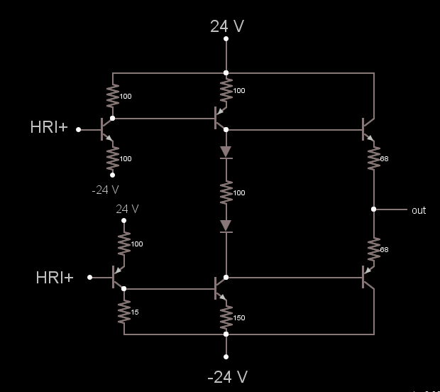
I want to calculate the open loop differential gain of the circuit assuming that HRI- and HRI+ are grounded.
My approach is to calculate the gain in the input stage (Q111 and Q112), the gain in the stage including (Q78 and Q114) and the gain in the output stage (Q94 and Q126) and multiply all the gains.
Please can I get some tips on how can I calculate the gain in the stage (Q78 and Q114)?
- - - Updated - - -
Here is my approach, I don't know if it is correct.
I have tried to calculate the gain in the stage (Q78 and Q114). The input resistance of Q94 is obtained as follows:
Rin94 = hFE*(R174 +re94) = 100*68 ohms = 680 ohms,
where hFE = 100.
Rtot2 = R155 // Rin94 = 150//680 = 122.892 ohms.
The gain in this stage As2= Rtot2/(R153+re78) .
But re78 = 25mV/Ie78= 25mV/5.3mA = 4.8 ohms.
Thus the gain in this stage As2 = 122.892/(150+4.8) = 122.892/154.8 = 0.794
To be able to calculate gain as multiplication you need to have infinite input impedance on the next stage and zero output impedance on the previous one.
Furthermore, Q94 and Q126 are Common Collector and the output between them, so maybe do it with both at the same time. Q78 and Q114 too.
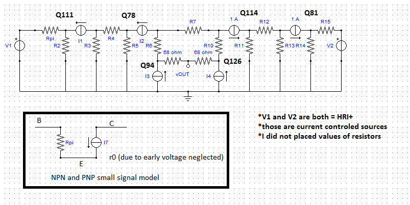
First, try to draw the whole circuit split in half like you did, call HRI+ - HRI- = Vin and when you split them , both will have Vin/2.
Make the analysis of one part and the other will be the same.
Draw the whole schematic and then apply Thevenin at stages as you did and the transistors will became into input resistances....
I am not sure on this approach because I have not studied this kind of circuits in depth this year..
I am really lost on how to continue. These are the questions I have to answer:
(1) Ground HRI- and HRI+. Calculate the operating currents on all transistors and the open loop output impedance at 1kHz. (2) Calculate the open loop differential gain of the circuit (connect input signal between HRI- and HRI+, ground other end).
I have done the calculations for the currents and simulated the circuit in LTSpice. My difficulties lie on the calculation of the open loop differential gain of the circuit (connect input signal between HRI- and HRI+, ground other end) and question 2
Here is the approach.
For the first stage: Av1 = Rtot/2re, where Rtot is the total resistance of R117 and the input resistance of Q78 which is Rin.
So the gain Av = Rtot/500 ohms. If hFE for Q78 is 250, Rin = hFE*(R115+re) = 250(155) = 38750 ohms.
So Rtot = R117//Rin = 14441ohms = 14000 ohms. Using this value the gain Av1 = 14000/500 = 28.
If the load is 10 ohms hFE for Q78 and Q94 are 250 and 100 respectively. Load impedance RL= (250)(100)(10 ohms) = 250,000 ohms.
Output resistance of Q78:
Using Early voltage of 50V, Ro = (VA + VCE)/IC. Ro = 10560 ohms.
The early effect resistance and and load impedance are parallel.
So Rtot2 = RL|| Ro = 74240 ohms. Gains at stage 2: G2 = 74240/155 = 480.
Gain for the first two stages G12 = G1*G2 = (28)(480) = 13412.
In reality the gain of the output stage is about 0.96 when driving 10 ohms.
So the open loop Gain = (13413)(0.96) = 12876. In dB = about 80dB
I have calculated the open loop gain considering a load of 10 ohms. I ended up with an open loop gain of about 12876 which is about 80dB. Is this feasible?
How do I take into consideration the 1kHz because the question says: Calculate the operating currents on all transistors and the open loop output impedance at 1kHz
I got the idea I used in the calculation above from the book: Designing Audio Power Amplifiers by Bob Gordell, Pages 44 to 48. It is well explained there but my problem how how the value of the load is selected.
Considering the output stage, For Q94, IE = 10mA, so re = 2.5 ohms. Making total emitter resistance Rtot3= R117 + re = 68 ohms + 2.5 ohms = 70.5 ohms = 70 ohms. But both halves are in parallel, so output impedance Zout = 70 || 70 = 35 ohms
This is how I calculated the output impedance, i don't know if it is correct
In the schematic on post #31, place a voltage soruce "Vx" between output and ground and consider a current flowing from it "ix" and make zero all independent voltage/current sources (i.e. V1 and V2). The output resistance is then Vx/Ix.
Av1 = Rtot/2re, where Rtot is the total resistance of R117 and the input resistance of Q78 which is Rin.
So the gain Av = Rtot/500 ohms. If hFE for Q78 is 250, Rin = hFE*(R115+re) = 250(155) = 38750 ohms.
So Rtot = R117||Rin = 14441ohms = 14000 ohms. Using this value the gain Av1 = 14000/500 = 28.
If the load is 10 ohms hFE for Q78 and Q94 are 250 and 100 respectively. Load impedance RL= (250)(100)(600 ohms) = 15000000 ohms.
SECOND STAGE: Q78
Output resistance of Q78:
Using Early voltage of 50V, Ro = (VA + VCE)/IC. Ro = 14360 ohms.
The early effect resistance and and load impedance are parallel.
So Rtot2 = RL|| Ro = 14346 ohms.
Gains at stage 2: G2 = 14346/155 = 93.
OUTPUT STAGE: Q94 and Q126
For Q94, IE = 10.3mA = 10mA
So re = VT/IE - 25mV/10mA = 2.5 ohms
This site uses cookies to help personalise content, tailor your experience and to keep you logged in if you register.
By continuing to use this site, you are consenting to our use of cookies.

 esigning Audio Power Amplifiers by Bob Gordell


