Continue to Site

Welcome to EDAboard.com

Welcome to our site! EDAboard.com is an international Electronics Discussion Forum focused on EDA software, circuits, schematics, books, theory, papers, asic, pld, 8051, DSP, Network, RF, Analog Design, PCB, Service Manuals... and a whole lot more! To participate you need to register. Registration is free. Click here to register now.

strange behaviour of SAW filters when unmatched

Status
Not open for further replies.

aaron_do

Member level 3
Joined
Dec 12, 2007
Messages
64
Helped
4
Reputation
8
Reaction score
3
Trophy points
1,288
Activity points
1,878
Hi all,


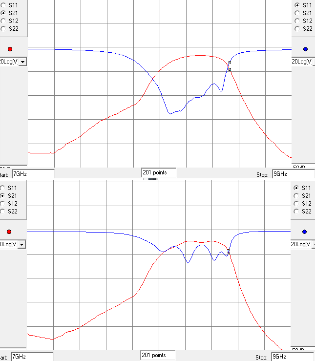
I am testing a design which uses a SAW filter as part of the chain, and I have noted that unless I pad the inputs and outputs with 50-ohm attenuators (about 3 dB each), the passband ripple is horrible. I have simulated (S-parameters) the SAW filter in its normal environment which is in between two amplifiers, and the simulation doesn't show any such ripple. I have been told that SAW filters, unlike other filters, misbehave when they are unmatched, but I wasn't given any further details. Can anybody explain this, or point me to a reference?


thanks,
Aaron
 

I believe this is true for all filters: when ports are mismatched characteristics change.
 

I suspect triple transit echo.

Thanks. That looks like it. Any clues as to why triple transit echo is not modeled by s-parameters?

Aaron

- - - Updated - - -

I believe this is true for all filters: when ports are mismatched characteristics change.

Normally the s-parameters themselves dont change (to my knowledge anyway)...
 

Aron, you are correct, s-parameters does not change. But filter response does. Image below illustrates it: on the picture response of some kind of coupled lines filter, empirical data (far from perfect, work in progress). On bottom plots port impedances are re-normalized to introduce mismatch. We can see ripples appearing.


Aron, you are correct, s-parameters does not change. But filter response does. Image below illustrates it: on the picture response of some kind of coupled lines filter, empirical data (far from perfect, work in progress). On bottom plots port impedances are re-normalized to introduce mismatch. We can see ripples appearing.


I understand that, but if you go back to my original post, I mentioned that this effect was not observed in simulation. I have the s-parameter models of all components involved, but simulation results don't predict the level of passband ripple that I'm seeing in my measurement (in fact the simulation shows hardly any passband ripple). Thanks anyway for your reply.


regards,
Aaron
 

" I have been told that SAW filters, unlike other filters, misbehave when they are unmatched"

This is an interesting thought though may be borderline to outrageous. As an extension of this thought would follow that SAW filter is non-linear device. This will raise some brows. Before exploring this path you obviously checked correctness of biases of power devices before and after the filter, measured s-parameters of circuits on board before and after and confirmed that measurements correspond to manufacturer's files you use in your model, you do not saturate any of the devices ... what else can be there? Could it be that any of semiconductors you use are fried? Then your measured s-parameters would differ ... any of the passive components cracked?

I just shook it up and down hoping the response would change :p...joking aside, I'm still in the midst of debugging. The main purpose of this post was to try and find out what effect my colleagues were referring to...

I was also wondering why this effect wouldn't be captured by s-parameters, and thinking that maybe the long transit times of the acoustic waves were messing with the phase measurements. On the other hand, I haven't been able to find any literature suggesting that triple transit echo cannot be measured by s-parameters, so now I'm leaning more towards this being just inaccurate modeling of my design...


regards,
Aaron
 

I know, give it a yank - problems may fall out...
Just for the sake of chatting I recommend removing the filter and measuring s-parameters of stage before and stage after the filter and 90% chance one of the stages will be off (with respect to your model). This way you localize your search to smaller area.
Another vague thought: some rf energy may by-pass your filter through the air. This can happen on higher frequencies close to connector-pcb transitions or some tall components. Such scenario may also lead to positive feedback and this may look like distortion of passband characteristics.
But I would start with option 1.
Good luck,
Andrey
 
Just for the sake of chatting I recommend removing the filter and measuring s-parameters of stage before and stage after the filter and 90% chance one of the stages will be off (with respect to your model). This way you localize your search to smaller area.

thanks. After some further tests, this does appear to be the issue...


regards,
Aaron
 

Do you know the part number/datasheet of the SAW filter? Are you sure that its ports are matched to 50 ohm. It may require L matching, possibly suggesteed in the datasheet.
 

Any clues as to why triple transit echo is not modeled by s-parameters?
Normally the s-parameters themselves dont change (to my knowledge anyway)...
It is true for LC filter such as dielectric BPF.

However it is not true for SAW filter.
SAW filter is based on electromechanical pheonomena.

Modes excited in SAW depend on terminations, drive impedance and load impedance.
Terminations are boundary conditions.

https://en.wikipedia.org/wiki/Electronic_filter#SAW_filters
 

Hi all,

The observed behaviour is typical of triple transit in SAW filters.
Triple transit effect happens in any two-port (any type of filter, not only SAW filters, even transmission lines) when there is mismatch at both ports.

The particular point with SAW filters is that they have a large group delay. Because of that, the echo produced by the forward-backward-forward path is observable as an isolated response, while in other type of filters (with low to moderate group delay) this response overlaps with the main one (forward-only path).

Think in a simple delay line with mismatches at both ends and excited with a short pulse: the triple transit is observable as echos following the main pulse.

The effect can be modeled by S-parameters. But the phase must reflect the real group delay.
It is usual to express the phase modulo 360°. For example, if a perfect delay line has a delay of exactly 10 cycles at some particular frequency you could say that s21 and s12 have magnitude 1 and phase 0 (if you perform a measurement at that specific frequency you see the output in phase with the input). But in that way you are considering that the 10-cycles delay line is the same as a zero-length line, and the effect of triple transit will be lost in the analysis.
In order to predict the correct results, you must preseve the 3600 degrees phase in the analysis.

The "triple transit" effect is observed as echos in time domain. In frequency domain, it is observed as ripple in s21 vs. frequency. The "period" of the ripple (difference of frequency between two consecutive peaks or valleys) is the inverse of twice the forward delay.

This effect is not related with nonlinearity or with variable parameters, as suggested in previous posts.

Regards

Z
 

I was also wondering why this effect wouldn't be captured by s-parameters, and thinking that maybe the long transit times of the acoustic waves were messing with the phase measurements. On the other hand, I haven't been able to find any literature suggesting that triple transit echo cannot be measured by s-parameters.
The answer may be quite simple. The s-parameters you got for the filter are either incomplete or incorrect. As already explained, a SAW has considerable propagation delay. Operating the filter unmatched at both ends enables waves to bounce back and forth, creating a kind of comb filter characteristic.

To see the propagation delay in s21 and s12 parameters, you need to look at the complex values that rotate fast over frequency, or the phase that is continuously increasing.

What kind of s21 and s12 parameters did you get for the filter? I guess, either the phase is ignored by showing only magnitude values, or they cancelled the propagation delay by applying a port extension calibration. So the propagation delay is hidden and can't be modeled in your simulation.

I presume that the observations can be explained by a purely linear model.

- - - Updated - - -

I reviewed SAW s2p parameters published by Epcos/TDK. They are obviously delay corrected to get real positive s21/s12 values. Unfortunately the behavior in a reflective circuit can't be correctly modelled with these parameters.
 

This effect is not related with nonlinearity or with variable parameters, as suggested in previous posts.
I don't mention any nonlinearity.
Boundary condition in differential wave equations is completley linear issue.
Different boundary condition can generate different modes.

And TTE(Triple Transit Echo) can be removed from frequency domain S-parameters by time domain gating techniques.
 

Attachments

  • 160326-153805.png
    160326-153805.png
    41.8 KB · Views: 66

I want to say are :
TTE(Triple Transit Echo) and
different mode excitation in SAW due to different termination(=Boundary Condition)
are another issues.

Latter effect results in different S-parameters.
However latter effect should be and has to be reduced.
 

The original question was why a SAW simulation with the published s-parameters doesn't show the passband ripple observed in a real measurement if you have impedance mismatch at both ends.

I agree with zorro that you don't need to refer to specific properties of a SAW filter to explain this behavior, except for the simple fact that the large group delay is omitted in the s-parameters.

I see that everyone agrees it hasn't to do with nonlinearity. But it has neither to do with different modes. If the SAW filter is a linear device, it can be treated as a black box and completely modelled by a set of complex s-parameters (which must be obviously constant). But only if the s-parameters are correct.
 

If the SAW filter is a linear device, it can be treated as a black box and completely modelled by a set of complex s-parameters (which must be obviously constant).
Wrong.
Even if the SAW filter is a linear device, a set of complex s-parameters can not be constant due to mode's difference.
 

Sounds like you are trying to reinvent linear circuit theory. Personally I'm not interested in this new science.

I'm quite sure that SAW filters can be well described as linear and time invariant systems.
 

Status
Not open for further replies.

Part and Inventory Search

Welcome to EDABoard.com

Sponsor

Back
Top