Continue to Site

Welcome to EDAboard.com

Welcome to our site! EDAboard.com is an international Electronics Discussion Forum focused on EDA software, circuits, schematics, books, theory, papers, asic, pld, 8051, DSP, Network, RF, Analog Design, PCB, Service Manuals... and a whole lot more! To participate you need to register. Registration is free. Click here to register now.

TIG Welder, inverter gate driver

Status
Not open for further replies.
Is better for the lower Rdson, but i still have a lot of unanswered questions and doubts....
1) why they put a so high negative bias?
2) why the gate trace with drain disconnected has not shown the ringing present in the lowside trace with transformers connected?
3) why the isolation trasformer pass DC and the output waveform is so similar to input waveform?
Sorry, may seem stupid questions, but i really like to learn.... Really thanks...

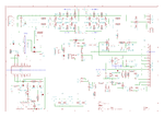
Another section of the welder:
Immagine.PNG
On the top board there what seem to me a suppression circuit for protect the mosfet from overshot of the inverter circuit.
 
I'm answering your questions even though I know that you wont accept them.
1. They didn't put high negative bias, they put the zeners wrong way round, probably an error.
2. The ringing is only in your oscilloscope and not on the board. You need the expensive probe to read the real signal.
3. The isolation transformer doesn't pass DC. You have to find where you are mistaking with you analysis.
 

for point 1) i will not be much surprised...
for point 2) i not have the right equipment, need to source something, need to look in auctions in ebay :p
For point 3, how do you explain the output waveform of the isolation transformer? Maybe i can disconnect the gate driver pcb and measure right the out of the transformer? All the components of the driver are in that scheme, no other diodes. The board is this one:
IMG_20160107_001246.jpg
The transformer is a toroid done with plastic isolated copper wire.
 

Inverter board:
inverter.PNG
The small circuit on bottom-sx is an oscillator for creating the 24v supply.
I not understand the function of the transformer T2, as there is only dc voltage here...
the AC board thermic switches only shut off a led hidden in the case of the welder, not so nice...
Next to do is the control board, where there is the 3525 ic...
Miss also the logic board, but it's a lot similar to the one in the pdf that i've posted previously...

For the zener question, i've searched the net other similar chinese welders and have the same gate drive circuit (with 5v negative bias), but with some minor modifications, like 3 parallel diodes for gate discharge and 3 220n capacitors for gate charge, so seem that is intended the 5v negative bias...
This is one:
ARC-font-b-welder-b-font-driver-board-welding-machine-driving-board-interface-arc250-315-400.jpg
Look the orientation of the zener.
In the meantime i'm searching a differential probe :)
 

Attachments

  • inverter.PNG
    inverter.PNG
    201.5 KB · Views: 224
And this is the control board...
control.PNG
I've not fully understood how works the voltage feedback from shunt resistor...
 
Sourced a second hand 25mhz differential active probe (quite cheap), this is the gate trace:
2v 1us.png
4v/div, 1us/div
The gate drive circuit is always the one shown previously.
There is the ringing, and the gate drive transformer actually output a square wave signal (also if i can't figure how)
 
The gate waveform looks very typical. The ringing at the start is caused by drain-gate capacitance, you get this ringing when the drain switches off or on.
The rounded wave is caused by the larger gate-source capacitance. You never get perfect square wave at the gate.
 
Looks identical to the previously posted low-side gate waveform, as it should. Not bad for a transformer driven gate.

You should be aware that a transformer with higher leakage inductance can change the single voltage drop during turn-on into sustained oscillations, risking fast transistor destruction.

The transformer will nevertheless reduce switching speed compared to an ideal gate driver and respective losses. But if the overall performance is still acceptable, the transformer gate driver makes an economical and straightforward solution.
 
Status
Not open for further replies.

Similar threads

Part and Inventory Search

Welcome to EDABoard.com

Sponsor

Back
Top