Continue to Site

Welcome to EDAboard.com

Welcome to our site! EDAboard.com is an international Electronics Discussion Forum focused on EDA software, circuits, schematics, books, theory, papers, asic, pld, 8051, DSP, Network, RF, Analog Design, PCB, Service Manuals... and a whole lot more! To participate you need to register. Registration is free. Click here to register now.

Two voltage sources in series -- second source powered by first? (Electric Vehicle)

Status
Not open for further replies.

chicowoodhill

Newbie level 4
Joined
Oct 19, 2006
Messages
6
Helped
0
Reputation
0
Reaction score
0
Trophy points
1,281
Activity points
1,350
I have an Electric Vehicle (EV). I replaced the original Nickle Metal Hydride (NiMH) batteries with Lithium Ion (LiON) batteries from a Ford Focus, and added a new charging system and battery management system (BMS). The traction pack is fully isolated from the vehicle chassis and electrical systems.

Even though it no longer manages the battery pack, I need to keep the old NiMH BMS functioning because it controls many of the vehicle's subsystems. To do this, I built a voltage divider that gives 25 taps off the new pack to spoof the original 25 batteries' voltage taps (I will eventually replace the pot with a microprocessor controller). This keeps the original BCM happy because it thinks it sees and is in control of the original pack. The BCM voltage sensing inputs are high impedance and draw virtually no current:

FULL SCHEMATIC.JPG

However, because the original NiMH pack and new LiON pack have different charge and discharge curves, the original BCM doesn't accurately track the SOC (state of charge) of the new pack. This affects the vehicle gauges and range. To compensate for this, I added an additional battery in series with the new pack so I can control the spoofed voltage to the original BCM. This allows me to fool it into seeing whatever cell voltages I want it to see. I have tested this idea and it works.

So my question is this: instead of using an additional battery to provide the boosted voltage I want, I'd like to replace it with a voltage source that is powered by one or more of the cells in the traction pack. But I'm confused about how to do this, since I don't know how to keep it isolated from its power source and mimic a standalone battery. My first idea is to use an off-the-shelf voltage booster for this, but again, I don't see how to power it from the pack and still put it in series with the pack voltage:
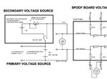
PARTIAL SCHEMATIC.JPG

I feel like the answer should be obvious but it escapes me...can somebody tell me how to add a secondary voltage source in series with a primary voltage source and draw the power for the secondary source from the primary source? ...thanks...
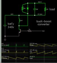
 

Start by referencing 0V as the top rail of your primary source. Then use a converter which inverts polarity. Its action can be based on switched-coil, or capacitive charge-pump.

A buck-boost converter is feasible. Example (going by your schematic):


Notice the 340V battery is the sole power source. The buckboost converter adds 24V above the positive rail.

The pulse generator can be low-voltage since it drives an NPN/Nmos placed near 0V ground.

It's up to you to determine whether your equipment is compatible with this configuration. You'll have to do some searching for a suitable commercial device, if there is one. Or construct your own, because converters like this are a popular project.
 
Thanks! This is what I was looking for...the circuit you provided is a good starting point and I think I'm cool from here.

One question, though...as to powering the pulse generator, would I be OK in connecting its ground to the Battery Minus, and maybe grabbing its Vcc (12v) from the positive terminal of the first 12v battery cell in the pack above ground? Looks to me like that would work but my concern is some ground loop path I might be introducing into the circuit...

ps. sorry for the delayed response...I thought I had set myself up for email notification...didn't see your post until my most recent login..thanks again...

A short cut is to use a product that exist. Any switching mode power supply 100-260VAC to 24VDC can do the job. Example:
https://www.ebay.co.uk/itm/Dymo-Lab...511636?hash=item5b088d72d4:g:H1EAAOSw7ThUdGo0
When you connect the 240VAC input to your 345VDC battery you get isolated 24VDC which you can connect to the top of the 345V.
In the power supply that you buy the AC input is always rectified to DC that converted to 24VDC. When you connect 345VDC instead of the mains the converter inside gets 345VDC which is the same as rectified 260VAC.
The polarity of the input to the converter is not important, you can also connect it to any part of the battery that gives at least 160VDC , which equivalent to 100VAC.

Wow, that's a great idea. I knew I had to incorporate isolation to make it work but it never occurred to me to use something like that wall wart. Nice.

I had found this type of device:

https://www.mouser.com/ds/2/281/kdc_mmv-764970.pdf

...and ordered a couple to see how they would work. Small and cheap, I don't need much current...but I like your idea better because I've got some of those sitting around, just waiting to be hacked ;)

And thanks for the explanation of how the device would handle HV DC. That would never have occurred to me...
 

One question, though...as to powering the pulse generator, would I be OK in connecting its ground to the Battery Minus, and maybe grabbing its Vcc (12v) from the positive terminal of the first 12v battery cell in the pack above ground? Looks to me like that would work but my concern is some ground loop path I might be introducing into the circuit...

Yes, it is not necessary to involve the entire battery stack. It makes better sense to draw from just one or two batteries, if your power needs are low.

Besides the buckboost converter, there is the capacitor-based charge pump (as found in voltage multipliers). It can derive a positive supply from negative pulses, by orienting the diodes as required.


This draws a 24V power supply from the top two batteries, and inverts it relative to the top rail (after subtracting a couple diode drops).

If you want to use only one 12V battery, then you must add a few more diode-capacitor stages, to get 24V.

- - - Updated - - -

Of course there is nothing wrong with using a storebought power supply (post #4). It's a question whether you enjoy tinkering, or, whether you trust your own work more than someone else's.
 
Status
Not open for further replies.

Similar threads

Part and Inventory Search

Welcome to EDABoard.com

Sponsor

Back
Top