Continue to Site

Welcome to EDAboard.com

Welcome to our site! EDAboard.com is an international Electronics Discussion Forum focused on EDA software, circuits, schematics, books, theory, papers, asic, pld, 8051, DSP, Network, RF, Analog Design, PCB, Service Manuals... and a whole lot more! To participate you need to register. Registration is free. Click here to register now.

[SOLVED] Crystal Oscillatror help

Status
Not open for further replies.

Eshal

Advanced Member level 1
Joined
Aug 29, 2012
Messages
470
Helped
16
Reputation
32
Reaction score
15
Trophy points
1,298
Location
Nowhere :)
Activity points
5,149
Can anyone tell me how to calculate the crystal frequency in the below attached figure?

Here is this.
Capture.PNG

How to get 4.194304. I think it is the standard value of the crystal. But how to get the nearest of it?
 

osc32.gifPierce Oscillator
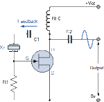
Another common design of the quartz crystal oscillator is that of the Pierce Oscillator. The Pierce oscillator is a crystal oscillator that uses the crystal as part of its feedback path and therefore has no resonant tank circuit. The Pierce Oscillator uses a JFET as its amplifying device as it provides a very high input impedance with the crystal connected between the output Drain terminal and the input Gate terminal as shown below.

Pierce Crystal Oscillator

pierce crystal oscillator


In this simple circuit, the crystal determines the frequency of oscillations and operates on its series resonant frequency giving a low impedance path between output and input. There is a 180° phase shift at resonance, making the feedback positive. The amplitude of the output sine wave is limited to the maximum voltage range at the Drain terminal.

Resistor, R1 controls the amount of feedback and crystal drive while the voltage across the radio frequency choke, RFC reverses during each cycle. Most digital clocks, watches and timers use a Pierce Oscillator in some form or other as it can be implemented using the minimum of components.
 

Sorry but I think you don't get what I really need to know. I am asking for how to choose the value of the crystal here? What calculation should I go for the value of the crystal? I know about its theory.
 

Crystal frequency is the output frequency..

MOSFET is used for amplification, Good stability factor
 
  • Like
Reactions: Eshal

    Eshal

    Points: 2
    Helpful Answer Positive Rating
You are looking at it the wrong way around Eshal, the crystal decides the oscillator frequency so you choose one for the frequency you want to produce. For example, if you needed a 5MHz oscillator you would choose a 5MHz crystal.

Brian.
 
  • Like
Reactions: Eshal

    Eshal

    Points: 2
    Helpful Answer Positive Rating
The crystal oscillator circuit uses a Jfet that is usually depletion, not a Mosfet that is usually enhancement. A Jfet bias itself to conduct and amplify then oscillate. A Mosfet would always be cutoff and will not work.
The crystal's frequency changes a little when its temperature changes.
The crystal oscillator's frequency is also changed a little by the stray capacitance of the wiring and of the Jfet, see the crystal's and Jfet's datasheets.

Many accurate crystal oscillator circuits have a temperature-controlled oven for the crystal oscillator and use a trimmer capacitor to adjust the frequency to be very accurate.
 
  • Like
Reactions: Eshal

    Eshal

    Points: 2
    Helpful Answer Positive Rating
@betwixt
It means first I know how much frequency I required then I will choose crystal?
If so, then can you tell me how to calculate the resistor's value as given in the diagram in post#1?

@Audioguru
I don't think that I need any oven. I have learned about temperature controlled oven in my course named, electronic communication. So I am aware of it.
 

That's right. The oscillator is basically an amplifier to overcome circuit losses (the FET) and a feedback mechanism to make it amplify itself. Putting the crystal in the feedback path stops it oscillating at any other frequency except the one the crystal is resonant at.

You can get crystals made to any frequency you like within the range of about 10KHz up to about 200MHz although there are frequencies used regularly for processor clocks or frequency standards which because of their popularity are available 'off the shelf'. 4.194304MHZ is a common frequency because it can be directly divided by 2 down to 1Hz and can also be used to set serial data rates when used a microprocessor system clock frequency.

The resistor value isn't critical, it's purpose is to hold the voltage at the FETs gate at near zero potential. As JFETs have very high input impedance it would drift if the resistor was left out. Any value from about 1K to 100K would work equally well.

Brian.
 
  • Like
Reactions: Eshal

    Eshal

    Points: 2
    Helpful Answer Positive Rating
Crystals can be operated at their series resonant or parallel resonant frequency. For your circuit, series resonant mode will apply. For simple pierce configurations as shown the resulting frequency will be slightly above the series resonance (5-10ppm) frequency of the crystal. To get it to operate exactly at series resonance of the crystal you will have to introduce some additional phase lag in the feedback path.

To summarize: Make sure you know if the frequency stamped on the crystal indicates its series or parallel operating mode frequency. Some good crystal manufacturers will often include "series" or "sr" stamped on the crystal. If you are dealing with a parallel mode frequency, you should use a Colpitts type circuit.

If you are having a custom crystal manufactured, they will ask you if it needs to be series or to specify the load capacitance for parallel operation.
 
Last edited:
  • Like
Reactions: Eshal

    Eshal

    Points: 2
    Helpful Answer Positive Rating
@betwixt
Thank you very for nice explanation.

@all
Why RFC is being used here?
Is there any specific difference between RFC and an inductor? Why it is not called an inductor?
 

Eshal said:
...
Why RFC is being used here?
Is there any specific difference between RFC and an inductor? Why it is not called an inductor?

An RFC is an inductor.

In this circuit it is called an RFC because that is its function. It essentially provides a very high impedance to your high frequency oscillations, but allows the DC supply to pass through.
 
  • Like
Reactions: Eshal

    Eshal

    Points: 2
    Helpful Answer Positive Rating
In this circuit it is called an RFC because that is its function. It essentially provides a very high impedance to your high frequency oscillations, but allows the DC supply to pass through.
It blocks high frequency oscillations where to go?
 

It blocks high frequency oscillations where to go?
An inductor has a high impedance at high frequencies (its reactance rises when the frequency rises). Then a transistor with an inductor as its collector load and has its emitter grounded has a high voltage gain at high frequencies.
Since the inductive reactance (impedance or AC resistance) is high then it blocks the oscillations from modulating the power supply voltage but it passes DC for the oscillator to work.
 
  • Like
Reactions: Eshal

    Eshal

    Points: 2
    Helpful Answer Positive Rating
That's what I want to ask. Audioguru understood what I wanted to ask. Thanks all.
 

Status
Not open for further replies.

Similar threads

Part and Inventory Search

Welcome to EDABoard.com

Sponsor

Back
Top