Continue to Site
Follow along with the video below to see how to install our site as a web app on your home screen.
Note: This feature may not be available in some browsers.
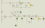
Are you sure the relay voltage falls short of minimum dropout voltage?
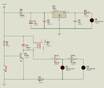
I am not using relay. I am using Solenoid (12 V). There is no Solenoid Valve in Proteus so I used relay.
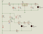
Here is the new circuit.
You mean to say that even 3 or 4 volts will operate the relay ?
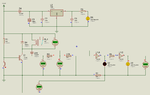
When relay is off I am getting 1.2V across relay coil which is 10 times less than its rating (12V).