Continue to Site

Welcome to EDAboard.com

Welcome to our site! EDAboard.com is an international Electronics Discussion Forum focused on EDA software, circuits, schematics, books, theory, papers, asic, pld, 8051, DSP, Network, RF, Analog Design, PCB, Service Manuals... and a whole lot more! To participate you need to register. Registration is free. Click here to register now.

How to draw Smith Chart in Agilent ADS.

Status
Not open for further replies.
Re: Help need for drawing Smith Chart in Agilent ADS.

jeeudr Sir,
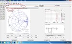
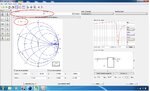
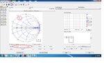
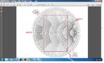
Thanks for your rigorous help. Now, I am able find the value of 0.872 (MAG) and 123(ANGLE) in the smith chart of ADS. Sir I am beginner for this ADS2009, now how I have to find the series line length and open stub length using this Gamma_S. I tried to find out, couldn't get it. I am not able to move the cursor at the outermost circle, cursor will be there in the inside the circle. How I have to find admittance point to the opposite to the Gamma_S. Finally I need to obtain the 0.206 lambda as open circuited length and series length of the line as 0.120 lambda in the smith chart.How to move the cursor and obtain these values.

I am coming nearer to the answer, please help me to resolve this difficulty.
 

Attachments

  • Gamma_S_drawn_using_ADS.jpg
    Gamma_S_drawn_using_ADS.jpg
    594.6 KB · Views: 99
  • POZER_Smith_Chart.jpg
    POZER_Smith_Chart.jpg
    933.4 KB · Views: 117
Last edited:
Re: Help need for drawing Smith Chart in Agilent ADS.

Dear Sir,
Kindly I request you to help me to resolve this Smith Chart difficulty.
 
Re: Help need for drawing Smith Chart in Agilent ADS.

The admittance point is just a refection about the origin of your original point. So you can plot 0.872 with an angle of -57(*) to get this opposite point.

If you are looking to recreate the exact image from Pozar, it is not possible with this ADS utility.

You can however solve for the lengths as explained numerous times in earlier posts.

(*) Magnitude will be the same, while the angle is obtained by subtracting 180 deg from your original angle
 
jeeudr Sir,
I got both admittance point and Gamma_S point.I am sorry that I tried lot to match the series and open stub length as shown in the you tube video, couldn't succeed it . I request you to show me , how to find the matching series and open stub length (not exactly similar to the Pozer example) if we know Gamma_S and admittance. Please show me graphical. It may be helpful for others also, who are looking for Smith utility help in ADS. I hope you will help me.
 

jeeudr Sir,
I request you to help me.
 

1. Set source impedance to 50 Ohm and load impedance to 0.872 at angle of 57 degrees. Lock both the values to the chart to prevent mistakes later.
Picture1.png

2. Click on the 'Line Length' button in the left palette to insert a transmission line into your circuit. As you move your mouse pointer over the Smith chart, the point will move along a constant VSWR circle. Add a rough estimation of the the length that you will need.
Picture2.png

3. Click on the 'Open stub' button in the left palette to insert a open stub into your circuit. It will move the point along the constant susceptance circle. Add the appropriate length to bring the point back to origin (50 Ohm).
Picture3.png

You can play with the values in 2. and 3. to obtain an accurate match. You can obtain the lengths by clicking on the components in the network schematic window to the bottom-right.
 
jeeudr Sir,
I tried as your said, am getting one thing correctly either series length or open stub length. I am able match to either series length 0.120 lambda or open stub length 0.206 lambda.One is coming properly, other is not coming properly.Which method we need to follow correctly to get proper results at 4GHz of series length and open stub length.
 

Attachments

  • Smith_Chart_Open_Stub_Length_0206.jpg
    Smith_Chart_Open_Stub_Length_0206.jpg
    644.1 KB · Views: 85
  • Smith_Chart_Series_Length_0.120_LAMBDA .jpg
    Smith_Chart_Series_Length_0.120_LAMBDA .jpg
    650.9 KB · Views: 85

I think that it should be fine. You will get multiple sets of correct answers. It does not matter which one you choose as long as it is consistent.

I think that I have given you all the basic steps needed for a simple impedance match using Smith chart. I am sure that you can learn much more from textbooks and other resources. So do use them, before continuing to post here.

There are a lot of subtleties in this impedance matching, see the following questions

(in increasing order of difficulty)

1. Why do you keep using open stub ? Why not a short-circuited stub ?
2. What exactly is the role of the series line and the parallel stub in terms of matching real and imaginary impedances ?
3. In the Pozar example, the curves are drawn in an anti-clockwise direction, while in ADS, the curves are being drawn in a clockwise direction ? Related topic is the difference between 'towards load' and 'towards generator (source)' directions.
4. Gamma_S is defined as the reflection coefficient when looking at the source from the amplifier input. So in a way, you are transforming from a 50 Ohm resistor to a Gamma_S. So why not set the load resistor to 50 Ohm and source to Gamma_S ?

Read through the theory in detail again and think about the above points.

If you think hard enough and use the Pozar book, I am sure that you can find the answers to your questions.
 
jeeudr Sir,
You helped me like anything, I am grateful to you. I will take your suggestions positively and work out. Thanks for your kind help for learning basics of Smith Chart. If you have any other youtube lecturing regarding SmithChart or PDF help about the Smith chart. If possible show me, help me.
 

Status
Not open for further replies.

Part and Inventory Search

Welcome to EDABoard.com

Sponsor

Back
Top