Continue to Site

Welcome to EDAboard.com

Welcome to our site! EDAboard.com is an international Electronics Discussion Forum focused on EDA software, circuits, schematics, books, theory, papers, asic, pld, 8051, DSP, Network, RF, Analog Design, PCB, Service Manuals... and a whole lot more! To participate you need to register. Registration is free. Click here to register now.

[SOLVED] Battery Recharging and Battery Backup Circuit???

Status
Not open for further replies.

xpress_embedo

Advanced Member level 4
Joined
Jul 5, 2011
Messages
1,154
Helped
161
Reputation
396
Reaction score
189
Trophy points
1,353
Location
India
Activity points
10,591
Hello!!! I am doing a Project on PIC32MX795F512L Controller, and have to use its RTCC, due to this reason i have to operate this controller even when there is no external supply, it works on 3.3V.

So i am using two AA Size Rechargeable Battery, i want a 1.5V+1.5V battery, but i think it is if 1.2V each, but its not an issue as i am using IC TPS61097.

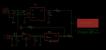
Here is my Schematic Diagram of battery backup and Recharging Circuit

PowerSupplyWithBatteryRecharging.png

I want to know is there any change that my battery gets damaged due to over charging as most of the times my external supply is there, only in some cases it is not there.

Please suggest me.
And if there is a chance that my battery gets damaged, than tell me the way to protect it.
 

so you are charging battery through 680R.
I assume your batts are nimh?
Below 1v/cell is bad for nimh, you shouldn't let them ever go below that really.
Also, max voltage for them depend on temp....but I would say something like 1.8V/cell....above that and you stop charging.
But batt datasheet should tell you charge /discharge regime /conditions etc.

Even when batt (2 in series?) is exhausted , your charge current is only V/R = 0.9V/680 = 1.3mA.....I DONT THINK YOU CHARGE IT WELL AT THAT LOW CHARGE RATE. (sorry caps)

Really you do need that datasheet...sometimes people do negative dv charge termination.......but that's not too much use when it gets small discharge then put back on charge.
 
Hello!!! Thanks for your reply

so you are charging battery through 680R.

Actually if found a circuit on internet, that's why used this, by increasing the value of resistor battery gets slowly charged and by decreasing it gets charged rapidly.

I assume your batts are nimh?

Yes i am using NIMH battery

Battery Link

I really dont know other specifications you are telling me, from where i can find datasheet of this battery and what to do, so that i can operate my pic32 for long period of time.
Please suggest me what to do, as i have to design pcb and for that purpose i had to completely test this circuit.
 
  • Like
Reactions: treez

    T

    Points: 2
    Helpful Answer Positive Rating
I would find a battery of a similar type, and look how that is charge , and then do the same with yours.

You should look up "negative dv charge termination" if you wish to use a cct for fast charging.
You may need temperature monitoring aswell if you do this.
..Or their are ways of charging it with c/10 or less......and maybe its a battery that can be constantly trickle charged?

if you charge it with a low current, it will take ages to charge up, but maybe that is ok for you?
If you do charge it with a low current, then you probably don't need to monitor the temperature of the battery during charging.

is every discharge likely to be deep , ? or shallow?

...if shallow then its difficult for you to do negative dv charge termination.

But you can sumtimes do re-charge of twice the charge that was extracted during discharge if you know this by "charge counting"
 
Re: Battery Recharging and Battery Backup Circuit?

hello treez

I use TPS61097-3.3V IC to boost the Supply to 3.3V but its not giving 3.3V at its output.

I construct this circuit and at the output had placed a 10uf Capacitor.

BoostBoard.png

i am not getting 3.3 volt at output, after that i replaced the Inductor of 10nH with 100uH as per datasheet, the required value is 10uH but as i dont have that inductor i had placed 100uH, when measuring voltage a output using Fluke Multimeter i am getting 1.8V and then constantly increasing when it reaches 3.5V i disconnect the battery. I am using two 1.2V Rechargeable Battery.

I think the voltage is increasing as i had not placed any load at the output, so place a 100 ohm resistor and with this i am getting 2.9V at its output.

I want to know why i am not getting 3.3V Constant.
 
  • Like
Reactions: treez

    T

    Points: 2
    Helpful Answer Positive Rating
ok, are you using big enough output cap?....try the 10uh inductor....is tps61097 switching at 1.2mhz?
 

I am using 10uF capacitor at output, and 100uH inductor.

I am using two Battery Cells of 1.2V each, in total which is giving 2.49V Output, but when i see voltage at output it is 2.9V

Why it is not 3.3V???

I don't have 10uH inductor with me, what is the effect of using inductor, is it the reason i am getting the less voltage at my IC Output.

- - - Updated - - -

I add this circuit to my PIC32MX795F512L board.

I had make a breakout board for PIC32 Controller just like this.

**broken link removed**

and this board is connected to a Motherboard PCB, the problem is that when i remove PIC32 breakout board, i get voltage 3.0V which is okay for me.

But as soon as i insert the breakout board in the pcb i get the 3.8V on Controller. :-(
 
  • Like
Reactions: treez

    T

    Points: 2
    Helpful Answer Positive Rating
have you scoped the 'L' voltage to see of the drain voltage looks normal?
Is yor inductor of enough current rating.?
has your inductor got low enough esr?

it says 10nhin yor schematic

where is the output diode in yor boost converter cct, I don't see it

wot is the tps61097's minimum allowable vin?
are you sure you are not overloading the output

is the output voltage smooth , or going up and down.
 

This is my Complete Schematic, this is how i am using battery and how i am charging it.

I had make the breakout board for controller, when i remove the controller i get 3.0V and when i insert the controller i get 3.8V
BoostIC.png

- - - Updated - - -

I am using Inductor of 100uH and i dont know its rating its quite big and i am assuming that it must have good rating.

Minimum input to TPS61097 is 0.9V

- - - Updated - - -

I connect load, then the output of TPS61097 is stable otherwise it goes up slowly i had check it upto 3.5V
 

Attachments

  • BoostIC.png
    BoostIC.png
    12.8 KB · Views: 132
Last edited:

I still can't see the boost converter's diode.
I see a diode after the output capacitor. ..........but where is the boost diode?
 

I still can't see the boost converter's diode.
I see a diode after the output capacitor. ..........but where is the boost diode?

What is Boost Diode???

I am not getting what term it is and what will it do..
 

from what you say, you are using a boost converter to boost up to 3.3V?
...A boost converter has a FET , a diode, and input and output caps, and a controller
...the fet , I presume is incorporated in the chip.....but where is the diode.

Draw a picture of a boost converter..........look where the diode is........you can maybe find a pic on wiki syay
 

I dont think so, we require a diode, the circuit i made is as per datasheet and EPE Magazine 2012 December issue.

Have a look at the Datasheet of TPS61097, it doesn't require any diode.
 

thanks...yes the diode is in the chip, I just had a look.
I think 100uh is too big, have you tried 10uh?
 

Status
Not open for further replies.

Similar threads

Part and Inventory Search

Welcome to EDABoard.com

Sponsor

Back
Top