Continue to Site

Welcome to EDAboard.com

Welcome to our site! EDAboard.com is an international Electronics Discussion Forum focused on EDA software, circuits, schematics, books, theory, papers, asic, pld, 8051, DSP, Network, RF, Analog Design, PCB, Service Manuals... and a whole lot more! To participate you need to register. Registration is free. Click here to register now.

50 Amps Battery Charger

Status
Not open for further replies.

Case Mod & AlertLinks.

By adding the voltage divider network the baby gets thrown out with the bathwater. Here the bath water is the 24 VDC and the baby is the mV drop across the shunt. I guess this is the reason they went ahead and invested in op-amps that can have input voltages equal to or higher than VCC.

Anyway I will draw and simulate the circuit in PROTEUS over the weekend and see how it works. My initial remark about the circuit is that the op-amp gain determination is likely to be ambiguous as the resistor on the input side is undefined and consists of a parallel combination of 4-5 resistors.

Zeb


What!?? We are clearly having a misunderstanding here 8-O
 
  • Like
Reactions: tpetar

    tpetar

    Points: 2
    Helpful Answer Positive Rating
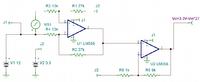
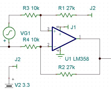
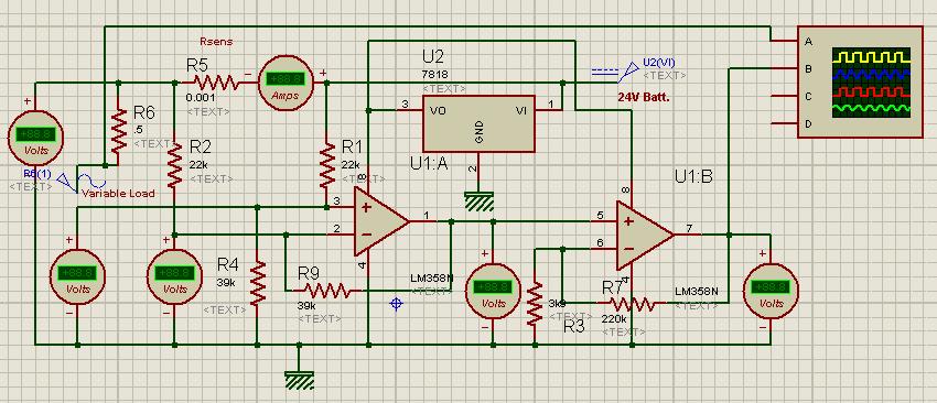
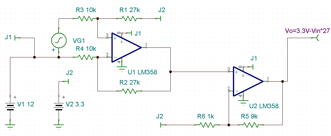
I found this schmatic on Ti's website. LM358 is used for Hi-side current sense.


I again need to emphasize. Please understand that there are UMPTEEN High side current sense ICs available int'ly. However these are not commonly available in Pakistan. I need to design with standard, easily available components - if possible discreet BJTs and FETs, so that once available in the public domain anyone can pick up the design, make a PCB and start marketing it e.g. Imran Bros. UPS kits. One can easily source from abroad, a Microchip or Atmel u-controller with current measurement systems pre-built into the chip. But that would be a one off thing WHICH is difficult to replicate for the ordinary small business/shopkeeper in Pakistan.

Zeb
 
Last edited:

LM358 is the most common IC available for Rs. 4
 
  • Like
Reactions: zeb59

    zeb59

    Points: 2
    Helpful Answer Positive Rating
LM358 is the most common IC available for Rs. 4


No luck. I downloaded and checked the datasheet. On page 15 there is an application circuit (Figure 25) for a Current Monitor. However there is a small note beside it which indicates the constraint that I have been talking about i.e. VL (in our case 24 VDC) should be 2 VDC less than or equal to VCC the supply to (+) pin of the op-amp (In our case 9 or 10 VDC).

So we are back to square one.

Zeb
 

5203608400_1380963949.jpg


Here again, voltage divider is used to overcome the limitation. You have find a way to use available components in your application as exact match is not available.
 

Another way is to make a voltage booster circuit to make a supply higher than battery voltage and then IC will treat +ve lead as negative. As current consumption is low, a simple diode pump voltage booster circuit can do.
I made the above circuit in Proteus and adopted it for 24V use.
3623238100_1380971446.jpg


I am attaching the proteus file
 

Attachments

  • Rsens lm358.rar
    13.3 KB · Views: 94
Another way is to make a voltage booster circuit


AlertLinks

Thanks for the circuit. However making a charge pump is out.

Anyway I seem to have made it work using a balanced power supply.

Schematic and PROTEUS files are attached.

Zeb
 

Attachments

  • longTail4.pdf
    9.9 KB · Views: 108
  • longTail4.rar
    11.5 KB · Views: 77

I think you made some errors in drawing. 1-ohm Resistor in series with the battery does not serve any purpose other than heating and not letting significant current to pass.
2775385500_1381312808.jpg

Biasing of transistors is wrong. Supply is 19V while voltage on bases of transistors rises upto 36V. Circuit does not simulate. There will be problem of thermal instabilty due to transistors being seperate. Further they are not matched pairs I suppose.
 

Sorry for the late reply. I was a little busy.

Yes the 1 ohm resistor is mostly redundant. In the actual circuit it will not be added.

I had used a balanced supply (+/- 19 volts) in the previous circuit. I have however revised it to a single supply basis, and attach it herewith.

You are right about the matching transistor issue. However I plan to use CA3028 which has a long tailed pair on a single substrate with matched HFE and so forth. It is an old IC and should be available cheaply (can you find out). That should allay your fears about thermal tracking. The current circuit is based on BC547s is just to test the concept, as CA3028 Spice model is not built into PROTEUS's libraries.

See if you can get the new circuit to work on your PROTEUS. It would also be fruitful to hear your comments on the new version after trying it out on PROTEUS. Currently the diff. voltage varies from 0 to about 280 uV. I'll add a 741 after it to amplify the voltage to a useful level.

Zeb
 

Attachments

  • longTail6.rar
    11.5 KB · Views: 76

Status
Not open for further replies.

Similar threads

Part and Inventory Search

Welcome to EDABoard.com

Sponsor

Back
Top