Continue to Site

Welcome to EDAboard.com

Welcome to our site! EDAboard.com is an international Electronics Discussion Forum focused on EDA software, circuits, schematics, books, theory, papers, asic, pld, 8051, DSP, Network, RF, Analog Design, PCB, Service Manuals... and a whole lot more! To participate you need to register. Registration is free. Click here to register now.

50 Amps Battery Charger

Status
Not open for further replies.
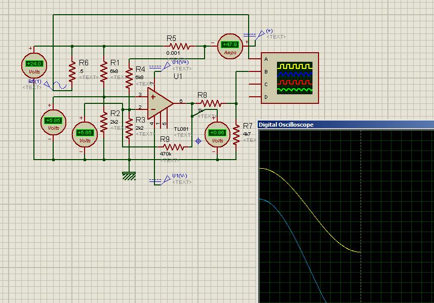
What resolution in reading you expect to achieve with current shunt 0,0004Ω (400µΩ) ?

Peter,

My purpose for this project is not specifically to design a charger but more generally a battery management system. Here in Pakistan we are in the midst of a serious energy crises with municipal power being available (worst case) for one hour in every two hours. So people use UPSs with automotive batteries. These automotive batteries are the main issue because excessive depth of discharge quickly ends their life in about 6 months or so. Normally available UPSs do not have smart battery management built in. Simple voltage based charge/discharge monitoring circuit is used with horrible consequences for the attached battery. Deep discharge batteries are either not available or are simply not affordable.

The above reality demands that a smart battery system should manage the battery. TO do so would require not only measurement of charge BUT ALSO DISCHARGE current which could go as high as 100 Amps+. Thus we cannot afford to have a high value shunt resistor because on the discharge leg of the system the shunt resistor will cause the problem of wastage of power etc.; that you have alluded to in your earlier post. So my circuit must have the capacity to measure current in the range of 1-100 Amps.

I hope the above explanation has clarified the matter.

My sense resistor in my amp-hour meter (mentioned in post #3), was a few inches of #12 copper wire.


Brad,

I would like to use a commercially available shunt. Ordinary Pakistanis are not likely to have the knowledge and skills required to homebrew a shunt. 60mv/100Amp shunts used with Analogue meters to display current are easily available in the local electrical goods supply markets. All these things should prompt someone to start manufacturing the management system.

Regards

Zeb
 

As you know, automotive batteries are not the best choice for this role. Instead they are designed to produce hundreds of Amperes for a brief time (that is, for starting an engine). Their lead plates are thin. Their useful life is not as great as deep-discharge batteries, or marine batteries.

Do you regard it as feasible for people to connect two or more automotive batteries in parallel? Or perhaps in series to obtain a 24 V system? It could be a way to combine two half-good batteries in order to get performance almost equal to a good battery.

As for draining too much from the battery, people will quickly learn that the more load they attach to it, the less time they can run it. They will need to decide what appliances they absolutely need. The trick is to avoid ruining the battery in the first few days before they learn the proper way to treat it.

I believe most inverters will shut off when the battery voltage drops to 10.5 V or so.

I do not understand what you intend to do about how much current is drained from it. Do you plan to cause a relay to disconnect it if the load is greater than 100 A?

What will prevent the relay from closing again immediately after it opens?

Moreoever besides arranging to keep the relay open, how will you make the system detect whether someone has reduced the load sufficiently so that it is okay to let the relay close again?

A meter to indicate battery condition is invaluable. A ten-LED bargraph to indicate voltage is simple enough. Or a ten-LCD bargraph would use less current (depending on how long the blackouts last).

To indicate the amount of current being drained, would it be sufficient to install five LED's? You could alert the user by putting red LED's at the highest one or two positions, and the lower LED's could be green.
 

I do not understand what you intend to do about how much current is drained from it. Do you plan to cause a relay to disconnect it if the load is greater than 100 A?

What will prevent the relay from closing again immediately after it opens?

Moreoever besides arranging to keep the relay open, how will you make the system detect whether someone has reduced the load sufficiently so that it is okay to let the relay close again?

Brad,

We are now getting into the nitty-gritty of the design. I have thought through some but have to apply my mind to others.

Your observations about the use of car batteries are very pertinent. However what does one do when outside temp is 43 degC. In deep summer temp. goes upto 50degC. So desperate measures require that we use whatever is available. However unless we do something to mitigate the issues, we will continue to suffer the same fate.

As you have mentioned, the normal shutdown mechanism is based on voltage (10.5 volts). I would like to go beyond that. I want to measure the charge depleted and on that basis replenishment of the charge. Voltage based end-of-charge regimes suffer from the issue of individual cell failure. If a cell becomes bad the voltage can never rise which means that charging never cuts off. It results in overheating overcharging of other cells etc.

A relay can be used to shut down power once depth of discharge reaches critical levels. I was thinking more in terms of using the transistors/mosfets in this role. These are anyway present in all UPSs/Inverters. The drive to the transistors/mosfets can be shutdown to cut off power. Also these should be usable in PWM mode for charging control for 3 stage charging.

As I submitted earlier I haven't thought through ALL these things. As you can see I am currently stuck at measuring the current to determine state of charge. Once I can go ahead I will work on the other aspects.

Zeb
 

In fact, the very lead used for connecting charger with battery can also play the role of sense resister. All you need is a seperate wire from battery clip to run along to go to current sense circuit inside the charger box. To detect current of load and to disable output in our ups, we use a tab 4 inches away from power module so that the joint stays in the box. This setup works very good upto 0.1A resolution, when checked with Amp-meter and works reliably. It is also used for controlling chaging current. LM324 operational amplifier is used in this circuit sensing voltage developed on -ve lead.
 

In fact, the very lead used for connecting charger with battery can also play the role of sense resister. All you need is a seperate wire from battery clip to run along to go to current sense circuit inside the charger box. To detect current of load and to disable output in our ups, we use a tab 4 inches away from power module so that the joint stays in the box. This setup works very good upto 0.1A resolution, when checked with Amp-meter and works reliably. It is also used for controlling chaging current. LM324 operational amplifier is used in this circuit sensing voltage developed on -ve lead.

I used that method myself for tests on several occasions, but would never use it for more than tests. For one requires adjustment, which is no more than doing a home made shunt, for other copper resistance does vary with temperature and its not necessarily linear. Also the poster said above he is not looking to make one:

I would like to use a commercially available shunt. Ordinary Pakistanis are not likely to have the knowledge and skills required to homebrew a shunt. 60mv/100Amp shunts used with Analogue meters to display current are easily available in the local electrical goods supply markets. All these things should prompt someone to start manufacturing the management system.

Regards

Zeb
 

I think you see these products and how they work and then impliment the functions in your own circuits after developing your own hardare.
https://www.ti.com/lit/an/slua450/slua450.pdf
**broken link removed**
A reqired parameter for good battery management is monitoring battery temprature and don't let lt to charge or dischage after a certain level exceeds.
 

In fact, the very lead used for connecting charger with battery can also play the role of sense resister.... It is also used for controlling chaging current. LM324 operational amplifier is used in this circuit sensing voltage developed on -ve lead.

AlertLinks,

The method you are using is a cost effective replacement of a shunt. However it has the issue of variation with temp. etc, as described by Casemod. But I think for charging current measurement in the +/- 5-10% range it should be a good cost effective system. The only issue I have is that you have this connected to the -ive lead which means you are using low side sensing, while I want to take the high side route.

I have played with the circuit (in my first post) on PROTEUS. It however completely refuses to provide any gain to the differential voltage developed across the shunt resistor connected in series with the battery. My hunch is that the circuit reads the differential voltage AS THE COMMON MODE VOLTAGE.

Can someone knowledgeable about theory shed some light on my hunch. If I am correct what corrective modification should I make in the circuit.

TIA & Regards

Zeb
 

The smart management you plan on requires an amp-hour meter. It is more work, of course. But it is the best method of tracking battery charge/discharge as well as overall health.
 

I think if starter batteries are used and discharged bellow 11,9V what is lower limit for starter, monitoring health is useless, even after first few discharging to 10,5V. Battery cannot be in good condition and health. Even new starter battery few days old can be killed with this usage. :)

Best world starter batteries allow around 200-400 cycles of total discharge (11,9V is 0% capacity and lowest point of discharge). Starter should not be discharged more then 30% this will prolong life of battery up to around 800-1000 cycles (between 70-100% of battery capacity or max 30% of discharge). Similar story is for deep cycle VRLA batteries, look to discharge up to max 40-50%. If you go with 100% discharge life is shorten.

Plus current rating must be respected C/10 (starter) and C/20 (deep cycle). If you drain 50A from 55Ah starter battery there will no be 55Ah, there is no 55A for 1h!!! Fastest possible discharge is 5,5A in 10h time or more to ensure production of 55Ah.

Peukert's law
http://en.wikipedia.org/wiki/Peukert's_law
http://all-about-lead-acid-batterie...amentals/peukerts-law-and-exponent-explained/


Best regards,
Peter
 

AlertLinks,

The method you are using is a cost effective replacement of a shunt. However it has the issue of variation with temp. etc, as described by Casemod. But I think for charging current measurement in the +/- 5-10% range it should be a good cost effective system. The only issue I have is that you have this connected to the -ive lead which means you are using low side sensing, while I want to take the high side route.

I have played with the circuit (in my first post) on PROTEUS. It however completely refuses to provide any gain to the differential voltage developed across the shunt resistor connected in series with the battery. My hunch is that the circuit reads the differential voltage AS THE COMMON MODE VOLTAGE.

Can someone knowledgeable about theory shed some light on my hunch. If I am correct what corrective modification should I make in the circuit.

TIA & Regards

Zeb

Why would you want to monitor the high side currents?

Regardless if you want to take the high side route, just put the shunt on the positive, cant see any issue with that. Unless you are trying to archive something else?

Regards
 

Why would you want to monitor the high side currents?

Regardless if you want to take the high side route, just put the shunt on the positive, cant see any issue with that.

The advantages of high side over low side are many. You don't have to put a resistor (The Shunt- however small) between Ground and the Battery negative terminal. The most important - if a short to ground occurs the current would not pass through the shunt. So the problem remains undetected. You can read the many papers available on the Net on this, which list the whole lot.

One cannot simply put the shunt on the +ive side and measure the voltage using an ordinary op-amp. This is because op-amps do not like to have their inputs close to the VCC supply voltage. They will latch-up. Manufacturers design special op-amps for this purpose which do not latchup when their inputs are close to or higher than VCC.

As I submitted earlier such op-amps; although easily available in Europe/USA, are difficult to source in Pakistan. Even if one can find one it is sure to be very expensive. That will deter the potential manufacturer (which are small scale businesses) from venturing into this field.

Zeb
 

Yes, they are referenced to VCC instead of GND. I used that approach for Pre-Charge circuit in Variable frequency drives design, whenever the HV- needs to be permanently connected to the DC-Link because some other equipment is using power from it.

I never had an issue with the short to GND. If properly designed the internal GND is not even accessible outside.

Its hard to know exactly what you want to archive without looking at the circuit. I also used current control on the primary whenever necessary. The currents are smaller and easier to manage with a 0.1Ohm 10W resistor. That would be my choice for a charger or other high power circuit where CC is needed. A Hall sensor is another viable alternative, mostly where isolation is required

Describe your application and goals in full.
 
  • Like
Reactions: tpetar

    tpetar

    Points: 2
    Helpful Answer Positive Rating


Here is to prove the concept,
circuit conditions are, load varies btween 0-nearly 50A sinosidal.
Voltage at output of TL81 is,

At 2.97A, output voltage is 3.97
At 21.0A load, ouptputt voltage is 2.73V.
At 47.9A, output voltage is0.86A
It remains within 5V for easy interfacing with mcu ADC. Caliberation can be done within mcu, if required.

Yellow trace is load current at 24V. It is an inverted trace. R is .001R Rsens. Green trace is voltage at IC output.


By overlapping he trace, nonlinearity is not observerd. Its only proteus simulation. An instrumental amplifier configuration will be more precise.
 

AlertLinks and Casemod,

First let me thank you both profusely for taking the time out for your input. My very special thanks to AlertLinks for drawing up the circuits in PROTEUS. Most obliged.

Casemod,

I have described my my goals earlier which I reiterate below. I may repeat that the implicit goal is to use "primitive" methods to measure high side current without resorting to special components which are either not available generally OR are too costly to introduce into designs because of a highly price-conscious market.

----
My purpose for this project is not specifically to design a charger but more generally a battery management system. Here in Pakistan we are in the midst of a serious energy crises with municipal power being available (worst case) for one hour in every two hours. So people use UPSs with automotive batteries. These automotive batteries are the main issue because excessive depth of discharge quickly ends their life in about 6 months or so. Normally available UPSs do not have smart battery management built in. Simple voltage based charge/discharge monitoring circuit is used with horrible consequences for the attached battery. Deep discharge batteries are either not available or are simply not affordable.

The above reality demands that a smart battery system should manage the battery. TO do so would require not only measurement of charge BUT ALSO DISCHARGE current which could go as high as 100 Amps+. Thus we cannot afford to have a high value shunt resistor because on the discharge leg of the system the shunt resistor will cause the problem of wastage of power etc.; that you have alluded to in your earlier post. So my circuit must have the capacity to measure current in the range of 1-100 Amps.

........ The normal shutdown mechanism is based on voltage (10.5 volts). I would like to go beyond that. I want to measure the charge depleted and - on that basis replenishment of the charge. Voltage based end-of-charge regimes suffer from the issue of individual cell failure. If a cell becomes bad the voltage can never rise which means that charging never cuts off. It results in overheating overcharging of other cells etc.

A relay can be used to shut down power once depth of discharge reaches critical levels. I was thinking more in terms of using the transistors/mosfets in this role. These are anyway present in all UPSs/Inverters. The drive to the transistors/mosfets can be shutdown to cut off power. Also these should be usable in PWM mode for charging control for 3 stage charging.
---------------

I do not have a circuit for the system worked out yet. The problem is how to measure high side current WITHOUT RESORTING TO HIGH COMMON MODE INPUT VOLTAGE OP-AMPS. (https://ww1.microchip.com/downloads/en/AppNotes/00894a.pdf. Please see the section on Advantages/Disadvantages of High side current measurement. Let me quote below the relevant part)
=====

Disadvantages:
•The VSENSE voltage is approximately equal to the supply voltage, which may be beyond the maximum input voltage range of the operational amplifier.


May require rail-to-rail-input op amps because of the high voltage level of the input signal. The high-side shunt circuit requires a high-voltage amplifier that can withstand a high common mode voltage. In addition, the key amplifier specifications are a high CMRR and a low VOS because of the relatively small magnitude of VSENSE. High voltage op amps and integrated differential amplifier ICs are available for systems that have a maximum voltage of
approximately 60V.
==========================

It is the high rail to rail input op-amps that I wish to avoid due to their unavailability and high cost. So I wish to use (preferably) a method such as BJTs to implement high side measurement.


AlertLinks.

The circuit you have very kindly drawn is OK. It is a normal difference amplifier implemented using a TL081 op-amp. However as I had submitted to Audioguru's post, the absolute maximum rating for inputs of the TL081 is 15 volts. Please note that the highest VCC possible is 18 VDC. So in effect the max input voltage must be 3 volts less than VCC supply. Since I plan to use a 24 VDC system the VCC will be at 24 VDC. In the circuit you have drawn, the behavior is OK because PROTEUS seemingly does not check for absolute max ratings being crossed. Apply 50 vdc to power supply pins of your circuits and probably you will still see the circuit behaving properly. However we know (without actually doing it) that 50 VDC will fry the chip.

Regards

Zeb
 

In the circuit, voltage supply for IC is 10V. The iputs of the IC are working near 6V. That's what resistor divider network do, to pull down the input voltage within the safe limits. Here I put voltmeters to monitor voltages are within safe limits as proteus does not warn when safe limit is crossed. Mains AC voltage with peak of 315V can be monitored if divider resistors are set accordingly without dammaging the IC.


At 12A and 51A load, input pins never exceed 6V. Output stays within 5V in full range to be directly connected to the ADC in MCU. Batttery is of 24V

I've got to admire your patience ;)

To keep the poster happy you could also place a resistor on the low side to make a floating GND for the supply

Since the voltage is measured on the high side the IC supply would be floating in respect to GND and could be regulated to a 15V (In respect to VCC) with a shunt regulator (Zenner). This would accommodate protection against transients since a 24V Charger can reach over 35V during an equalisation charge
 
Last edited:

Yes, but in addition to adding more complexity to the circuit, the output may not be directy connected to 5V ADC.
 

Yes, but in addition to adding more complexity to the circuit, the output may not be directy connected to 5V ADC.

I was assuming this voltage to be shared with the ADC as well.

As the poster said, some kind of regulation is required to keep the TL081 within its operating voltage, not just 21-32V as this setup can provide. The simulation is not taking that into account. The inputs are protected, but not the main supply voltage.

A high side shunt means the reference is VCC, so a normal positive regulator of some kind would subtract from VCC. The only viable options are an isolated DC-DC with its output positive attached to the VCC, have all the electronics regulated from the negative supply, hence a floating GND to keep the supply voltage within safe values, but referenced to VCC or an OP-AMP that can withstand 50V to accept maximum battery voltage plus transients.

Also I would personally not use voltage dividers since he's reading a shunt. Assuming there will only be a few mV at maximum current, when properly referenced to VCC voltage dividers will not be required. I know you are using a different approach, but I would not do it that way. I would see VCC as my virtual Zero and the voltage would build up with the current. This is what dedicated high side op-amps do. I believe what you are doing is to read the maximum voltage and subtracting from whatever is provided by the shunt, which would also work, but maybe a bit more complicated. Its fine for voltage monitoring tough.

Also on, say a 100mV/50A shunt (that would dissipate 5Watts at 50Amps), using a 1/4 voltage divider the precision will be 4 times less. Assuming say 100mV @ 50Amps, with the voltage divider of 1/4 thats would be 25mV per 50Amps or 0.5mV per A, In real world makes it quite hard to measure low currents and any magnetic field may cause a small voltage enough for an error. At such low voltage levels noise can be a real issue.
 
Last edited:

The IC supply Vcc is set to 10V in power rail configuration. It is not connneced directly with battery. In other words a regulator IC is pesent there.
Input is also of very low impedence, the interval of taking ADC samples could be hudreds of mili-seconds (and averaged over many seconds), so a lowpass filter will eaily remove noise. ADC resoluion requires another look. Charging may be 85% to 95% efficient depending on the batery and chaging current and temperature. As battery gets older, more power is wasted and converted into heat. Battery capacity also decreases. Now it can't be charged using capacity calcultions alone, it will be over charged. Practically, only a rough estimate will be achieved, other charging techniques such as monitoing battery voltage and tempature still have to be incorporated.Similalarly is in the dicharging case. With higher currents interal rsistane will waste more energy but it wll not be calculated.
What will be the response when battery electrolyte is below minimam level? Actually I thought on these lines when I had the idea to impliment calculating in/out power to and from the battey. I wrote the software and simulated it. It shuts off charging when power consumd for charging is 140% higher than the discharged power or maximum time for charge is crossed with indication of battery fault. It had three stage standard charging cycle. In adition it continued charging once started for some minuits. Some battries with slight sulfation can benifit. I never tested it into hardware. For healthy battery the three stage charging cycle works good. When a fault is occured in the battery e,g, any cell becomes short, only a function which limits maximum allowed charging time ( for example set to four houres and the giving indication of battey fault and stopping charging unless attended) can save the battey bank.
 

Also on, say a 100mV/50A shunt (that would dissipate 5Watts at 50Amps), using a 1/4 voltage divider the precision will be 4 times less. Assuming say 100mV @ 50Amps, with the voltage divider of 1/4 thats would be 25mV per 50Amps or 0.5mV per A, In real world makes it quite hard to measure low currents and any magnetic field may cause a small voltage enough for an error. At such low voltage levels noise can be a real issue.

Case Mod & AlertLinks.

By adding the voltage divider network the baby gets thrown out with the bathwater. Here the bath water is the 24 VDC and the baby is the mV drop across the shunt. I guess this is the reason they went ahead and invested in op-amps that can have input voltages equal to or higher than VCC.

Anyway I will draw and simulate the circuit in PROTEUS over the weekend and see how it works. My initial remark about the circuit is that the op-amp gain determination is likely to be ambiguous as the resistor on the input side is undefined and consists of a parallel combination of 4-5 resistors.

Zeb
 

Status
Not open for further replies.

Similar threads

Part and Inventory Search

Welcome to EDABoard.com

Sponsor

Back
Top