Continue to Site

Welcome to EDAboard.com

Welcome to our site! EDAboard.com is an international Electronics Discussion Forum focused on EDA software, circuits, schematics, books, theory, papers, asic, pld, 8051, DSP, Network, RF, Analog Design, PCB, Service Manuals... and a whole lot more! To participate you need to register. Registration is free. Click here to register now.

50 Amps Battery Charger

Status
Not open for further replies.

zeb59

Junior Member level 3
Joined
Sep 13, 2012
Messages
25
Helped
1
Reputation
2
Reaction score
1
Trophy points
1,283
Activity points
1,597
Hi,

I am trying to design a 50 Amps capable battery charger for charging a 2000 AH lead acid battery bank.

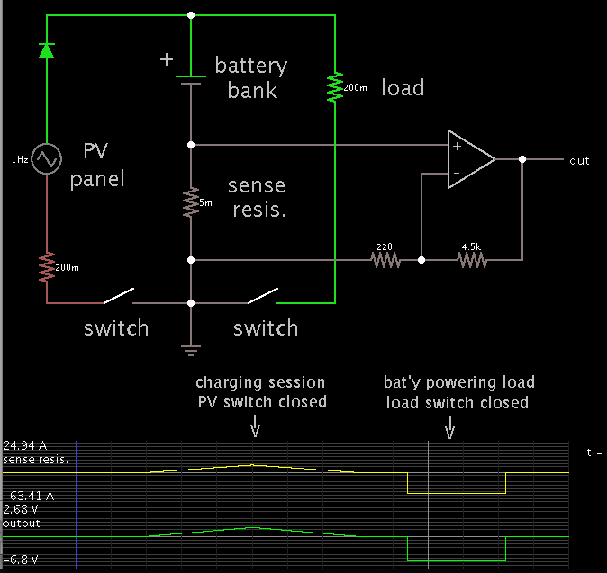
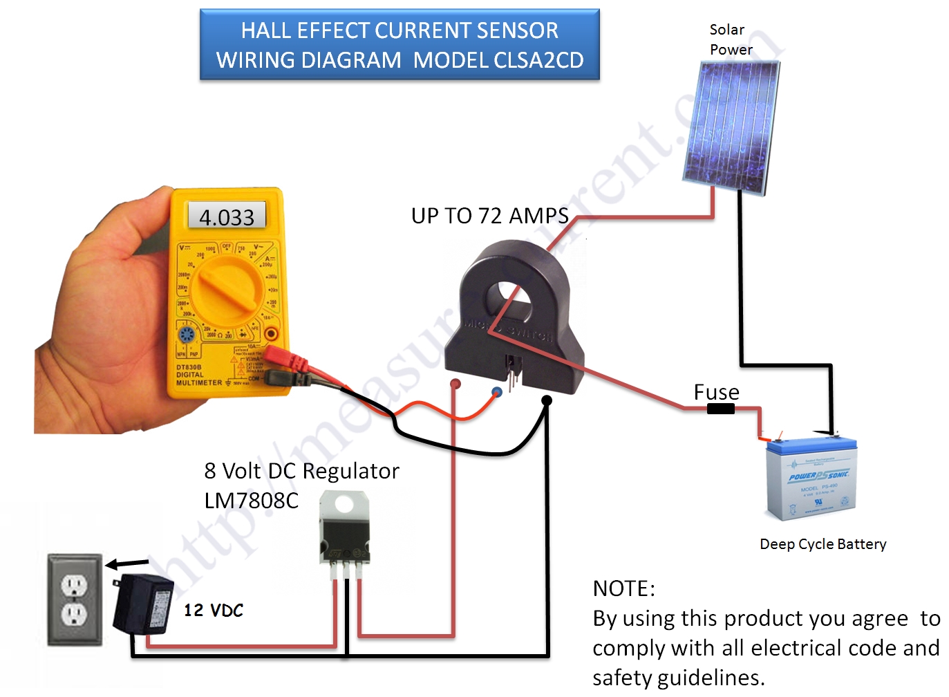
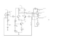
For the above purpose I would like to measure the battery charge/discharge current. I initially tried ACS712 because it offers the possibility of galvanic isolation. However that route had to be abandoned because voltage has to be measured which means galvanic isolation is not possible. Now I am toying with high-side measurement of current. The problem here in Pakistan is the non or difficult availability of high side measurement ICs. So I am trying to do some ab-initio design of the input stage using discrete components (or CA3086 type) matched transistor array. The array would be followed by an IN-AMP (I am using the easily available AD620). The current measurement is by a shunt resistor (0.0004 ohms). My initial circuit using BC547 BJTs is shown below:


I would like the forums valuable views on the design and any corrections that I should incorporate.

TIA

Zeb
 

The transistors will probably not be matched causing a high input offset voltage and even temperature changes will change their output voltage.
There are many ordinary opamps like the TL081 or TL071 that can measure high side and can have an input offset nulling pot. Then the IN-amp is not needed.
 

1.

I had a similar battery bank. Tens of Amperes running in and out of it. I set out to construct an amp-hour meter.

To convert current to voltage, I installed a sense resistor near ground, and amplified the voltage with a plain op amp:


I powered the op amp from the battery alone, hence it could only measure charging current. (To measure current exiting the battery would require a negative supply as well.)

I had to add a high-ohms resistor to the positive supply, in order to adjust the output to be zero when no current was flowing.

2.

Along a different line...

I found a very useful ammeter was the magnetic type, marketed for measuring heavy starting and charging current in vehicles. It works very much like a compass.

Although the catalog listing called it an 'inductive meter', it really was more like a magnetic needle, which moved across a graduated scale. It returned to center when no current was flowing, therefore it apparently had a weak spring return.

I believe it should be possible to take a tiny magnet, and make your own meter.
 

ACS712 is up to 30A what I know, ACS709 and ACS710 are for up to 75A. Current flows direct through that sensor. Better look to use A1302 Hall sensor (its replacement for UGN3503), this sensor dont require direct connection with wire, you need just a ferrite.

**broken link removed**

ACS712
**broken link removed**

A1302 (UGN3503)
images


**broken link removed**

**broken link removed**


clsa2cd-measure-current.jpg


http://archive.siliconchip.com.au/cms/A_30551/article.html

30551_12mg.jpg


Best regards,
Peter
 
Last edited:

Thanks guys for the responses.

Audioguru,

I looked at the TL081 datasheet. The absolute max rating for the op-amp input voltage is 15 volts. I am using 24 VDC battery. So the TL081 is out.

The BJTs used in the figure are out of necessity because PROTEUS does not have the data of CA3096 built into its library. If you look at CA3096 datasheet you will find that it has 5 BJTs on the same substrate which means their HFE and VBE movement with Temp. will be matched. These ICs are also good upto 24 volts so these can be readily used for my 24VDC system.

BradtheRad,

You used low side measurement in your circuit. That is my second option if I cannot make high side work.
Your second suggestion about using the meter is not useful for me as I intend to use a u-controller as the battery charger must be intelligent. I want to use it to charge batteries using both AC mains, and solar when AC mains is absent. So the purpose of the differential circuit is to feed into a microcontroller's A to D converter which will manage the charge/discharge of the battery.

Tpetar,

My problem is with the availability of ACS ICs in Pakistan. The 712 is available but it is highly unlikely that the higher current version would be available. As I submitted earlier I have already abandoned the ACS route, so I don't intend to return to it.

Zeb
 
Tpetar,

My problem is with the availability of ACS ICs in Pakistan. The 712 is available but it is highly unlikely that the higher current version would be available. As I submitted earlier I have already abandoned the ACS route, so I don't intend to return to it.

Zeb


I suggest A1302 not ACS family of Hall sensors, its complete different as you can see on illustrations.


Best regards,
Peter
 

Audioguru,

I looked at the TL081 datasheet. The absolute max rating for the op-amp input voltage is 15 volts. I am using 24 VDC battery. So the TL081 is out.
No.
The maximum voltage BETWEEN inputs is 30V. With a plus and minus 15V or plus and minus 18V supply, the maximum allowed input voltage is plus or minus 15V.
You have a single-polarity supply so the input voltages can be as high as the supply voltage or +30V whichever is less.

The BJTs used in the figure are out of necessity because PROTEUS does not have the data of CA3096 built into its library.
The antique CA3096 was designed and made many years before computers were invented. Is it still available?
 

I often use a hall sensor. Similar to the approach given above.

Something like a LEM HAL50S will output a linear voltage according to the current flowing on the conductors. (Either positive or negative) A 1W +/-15V DC-DC Converter is used to power such device. The Hall sensor Output can be set as a feedback to the voltage regulation loop on the power supply reducing the voltage to archive CC.

If you only need the charge current you can use a cheaper alternative with a single power supply.
 

Something like a LEM HAL50S will output a linear voltage according to the current flowing on the conductors.


Whilst all these approaches are possible, the main problem is the availability of various ICs and sensors. That is the reason I had to resort to the differential pair using discrete matched BJTs.

As per my original request please guide me about this approach.

Audioguru. Yes the CA3096 is archaic, but still available locally.

Regards
 

The absolute max rating for the op-amp input voltage is 15 volts. I am using 24 VDC battery. So the TL081 is out.
TL081 is not out. You can use voltage divider network to lower input voltages.
 

You do not need a voltage divider for the input. The maximum input voltage is 15V when there is a dual plus and minus 15V supply. Then an input can be 30V above the negative supply pin which is 0V in your single-polarity supply circuit.
The input works fine at a single-polarity positive supply voltage as high as 30V.
 
  • Like
Reactions: zeb59

    zeb59

    Points: 2
    Helpful Answer Positive Rating
Thanks everyone.

Audioguru

Let me test the TL081 whether it latches up or not at 24 VDC. Its only Rs.50/-

Zeb
 

A TL081 will not latch but it has a problem called "Opamp Phase Inversion" where the output suddenly goes high if an input voltage goes within a few volts from the negative supply pin voltage (0V in your circuit).
 

Attachments

  • opamp phase inversion.PNG
    opamp phase inversion.PNG
    15.3 KB · Views: 106

Have a look at the MAX4080. They have a free samples service to ship to you.
 

Have a look at the MAX4080. They have a free samples service to ship to you.

Usage of shunt resistor for measuring current is waste of power, specially at higher currents above 10A, in that case you get heater element for winter. Of course there is many pro maded current shunts even for 150A and more, but in solar and other alternative power sources its good to pay attention on all loads, and to reduce all power loss.

For sure current shunt will do the job, but I will say at what cost (power waste).


Best regards,
Peter

;-)
 

Have a look at the MAX4080. They have a free samples service to ship to you.

Neddie,

As I submitted in my opening post all these ICs out there are not available in Pakistan. I am in fact trying to develop this charger for placement in the public domain (see below) so that somebody with a commercial intent can make and market. Access to sophisticated electronic components in Pakistan is limited.

**broken link removed**


Therefore the design exercise is deliberately based on using simple, easily available components.


Audioguru.

I found the following on a google search on phase inversion, on the ANALOG website

**broken link removed**

----------------------

A common problem encountered with JFET op-amps is phase inversion. If the input common-mode voltage of a JFET op-amp approaches the negative supply too closely, the inverting and non-inverting input terminals reverse functions. Negative feedback becomes positive feedback and the circuit may latch up. This latchup is unlikely to be destructive, but power may have to be switched off to correct it. This figure shows the effect of such phase inversion in a circuit where latch-up does not occur. The problem may be avoided by using bipolar amplifiers, or by restricting the common-mode range of the signal in some way.


A more serious form of latchup can occur in both bipolar and JFET op-amps if the input signal becomes more positive or negative than the respective op-amp power supplies. If the input terminals go more positive than +Vs + 0.7 V or more negative than -Vs - 0.7 V, current may flow in diodes which are normally biased off. This in turn may turn on thyristors (SCRs) formed by some of the diffusions in the op- amp, short-circuiting the power supplies and destroying the device.

To avoid such destructive latch-up it is important to prevent the input terminals of op-amps from ever exceeding the power supplies. This can have important implications during device turn-on: if a signal is applied to an op-amp before it is powered it may be destroyed at once when power is applied.
-----------------
I have personally experienced the turn-on issue in a design using an AD620. We destroyed 2-3 chips before we figured it out. It was an RTD based temp measurement circuit in a bridge config.

My design will have a 24 VDC battery. The electronics will be powered from the same battery. I will be reducing the power supply voltage to something like 18 VDC by using voltage regulation in order to ensure a clean supply to the analogue voltage measuring electronics. Thus the voltage at the inputs of the op-amp will be 24 VDC which is 6 volts higher than the supply (3 volts in +/- supply mode).

The fact that TI and other chip manufacturers market chips that are specifically designed to withstand input voltages higher than power supply voltage, is indicative of the fact that this will be an issue.

Tpetar

I think measuring current using shunts is nothing new. Even the most modern u-controllers use this approach. The waste of energy you refer to is minimal and can be seen as the cost of doing business.

Zeb
 
Last edited:

Tpetar

I think measuring current using shunts is nothing new. Even the most modern u-controllers use this approach. The waste of energy you refer to is minimal and can be seen as the cost of doing business.

Zeb

Yes its old way to sense voltage drop/current, but unfortunately with side effects of power waste. Modern uC dont use that approach, modern and even old dont use current shunts for operation at all, shunt is additional part of circuit and its not linked with uCs.


The current measurement is by a shunt resistor (0.0004 ohms).

What resolution in reading you expect to achieve with current shunt 0,0004Ω (400µΩ) ?


Its your project, you can use what you want and what you think what is best for you. Its not bad to see what companies do for their commercial products, or to see some finished good projects. Its good to start with something, if you have trouble to get parts, then use current shunt why not. At least for first version of device, always you can improve device in next versions.


Best regards,
Peter
 

My sense resistor in my amp-hour meter (mentioned in post #3), was a few inches of #12 copper wire.

I designed the meter to measure up to 20A.

The wire generated sufficient voltage across it so that I could amplfiy it with a plain op amp.

The selection was a tradeoff among these factors:

* I wanted to waste minimum power.
* A sufficiently thick gauge was needed, as I went according to ampacity tables.
* My small enclosure had enough room that I could loop several inches around the inside.
 

Status
Not open for further replies.

Similar threads

Part and Inventory Search

Welcome to EDABoard.com

Sponsor

Back
Top