Continue to Site

Welcome to EDAboard.com

Welcome to our site! EDAboard.com is an international Electronics Discussion Forum focused on EDA software, circuits, schematics, books, theory, papers, asic, pld, 8051, DSP, Network, RF, Analog Design, PCB, Service Manuals... and a whole lot more! To participate you need to register. Registration is free. Click here to register now.

Will this circuit work?

Status
Not open for further replies.

syedj94

Newbie level 4
Joined
Aug 12, 2013
Messages
7
Helped
0
Reputation
0
Reaction score
0
Trophy points
1
Activity points
52
Hi,
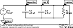
I am trying to make a "battery" for my snow blower(uses 24V) that can be plugged in. I am going to use this schematic I made. Will this work? I am planning on giving the capacitors a charge with 120 volts ac and then removing the charge and using two capacitors so that they charge them selves, and last the "battery" for approximately 60-90mins.
Thanks!
 

Attachments

  • battery-circuit.png
    battery-circuit.png
    27.3 KB · Views: 112

It will not work for several reasons:

1. You can't charge capacitors with AC.
2. The capacitors are wired in series with the output instead of across it.

In any case, using such huge capacitors will cost more than it's worth and would be several times the size of the snow blower!

Brian.
 
Sorry.. the scematic has an error. It uses 4700uf capacitor.
Suppose I use a DC adapter to power the circuit?
Btw, how to I wire the capacitors across the output?
 

You wire the DC adaptor across the capacitors to charge them then reconnect the capacitors across the load (snow blower) to use the energy they have stored.

You should note that 9,400uF (the combined value of 2 x 4,700uF in parallel) will probably only power the blower motor for maybe 1/10th of a second! The values need to be VERY much higher to be of use and bear in mind that unlike a battery or adapter, their voltage starts to decay toward zero as soon as you draw current from them.

Brian.
 
The wire connection across R3 shorts out the resistor and both capacitors...making all three invisible to the circuit. Even without the wire, they are all invisible to the circuit.

Ken
 
do you have another idea to make a snowblower wireless?
 

You will have to tell us the specification of the snow blower first. Somewhere on it there should be information on it's power rating, for example the working voltage and current or possibly a VA or Watts number. The more information you can give the better we can advise you.

Brian.
 

suppose I connect for 4700uf capacitors in a parellel circuit, and each capacitor connected to a 10Mohm resistor, and all the resistors connected together and going into a boost converter, and the output of the boost converter going into a dc/ac converter. Would this work? I am using the t=rc formula. I also used this calculator: http://hyperphysics.phy-astr.gsu.edu/hbase/electric/capdis.html#c2
I put 10Mohm for R, 4700uf for C and 30 for V out, and the discharge time is 4700 seconds, seems enough to me(ANYTHING IS BETTER THAN HANDLING A HEAVY CORD IN THE SNOW!!)

- - - Updated - - -

The wire connection across R3 shorts out the resistor and both capacitors...making all three invisible to the circuit. Even without the wire, they are all invisible to the circuit.

Ken

should I remove the ground connection to the resistor?

- - - Updated - - -

Suppose I also added inductors, would that increase current?
 

Where did the 10Mohm resistor come from? You can not power device with 10Mohm resistor in series. Instead of 10Mohm, use impedance of Your snow blower motor in Your calculation and You will see the reality...
 

(ANYTHING IS BETTER THAN HANDLING A HEAVY CORD IN THE SNOW!!)
rings alarm bells. It sounds like this snow blower is AC mains powered so it's power consumption is going to be very high, I would guess in the 1 - 2KW region.

This means it needs:
1. AC, your circuit, if it worked, could only store DC.
2. More power than you could sensibly hold in capacitors.
3. Either 110 or 230V RMS voltage.

Even if you could store the power in capacitors, the current from them would have to be (assuming 1.5KW load and 12V capacitors) 1500/12 = 125 Amps! In reality that would drain 9,400uF to nothing in a tiny fraction of a second and the circuitry needed to boost 12V DC to the AC line voltage would make it even faster. I'm afraid the power demand you are making is just too high for that kind of storage and you have no practical option but to use that heavy cord. If you really do want to go cordless, your only chance would be with a large car battery and high powered inverter but even that wouldn't last long and would be very expensive and heavy.

Brian.
 

There is a big difference between battery and capacitor... Ordinary capacitors cant be used as battery for a KW load... better dont make a Battery. Use a Battery and design the rectifier and inverter circuits.. That will make it wireless and will give you a good practice...

The battery is Too heavy because it has a less energy density. (holds lesser energy than a mechanical petrol or diesel engine) There are some lesser weight batteries with some more cost.

Regards,
Venladesh M.
 
Last edited:

So a capacitor bank would not work would it?
:(
 

Status
Not open for further replies.

Similar threads

Part and Inventory Search

Welcome to EDABoard.com

Sponsor

Back
Top