Continue to Site

Welcome to EDAboard.com

Welcome to our site! EDAboard.com is an international Electronics Discussion Forum focused on EDA software, circuits, schematics, books, theory, papers, asic, pld, 8051, DSP, Network, RF, Analog Design, PCB, Service Manuals... and a whole lot more! To participate you need to register. Registration is free. Click here to register now.

1 bit Rising-edge detector in verilog hdl

Status
Not open for further replies.

comp_engineer

Newbie level 5
Joined
Mar 23, 2013
Messages
10
Helped
0
Reputation
0
Reaction score
0
Trophy points
1,281
Activity points
1,385
hi everyone

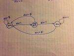
I'm writing a Moore FSM for a rising-edge detector in Verilog HDL. I have essentially written the module but I am not sure as how to transition from the "edge" state to the one state. Please look at the diagram I drew that is attached to this post. Here are my design stipulations:


A rising‐edge detector is a circuit that generates a one clock‐cycle pulse every time the input signal din changes from 0 to 1.

The detector also receives the clock signal CLK and a reset signal RESET and generates the output signal pe.

Use zero as the reset state.


and here is my Verilog code, perhaps someone can give me a few pointers


Code:
`define zero 1'b0
`define one  1'b1


module MooreFSM(clk, reset, din, pe);

input clk, reset, din;
output reg pe;

reg out;
reg state;
reg next_state;

always@(posedge clk) begin
	if(reset) state = 1'b0; //if there is a reset signal the state goes to state zero
	else		 state = next_state;
end

always@(din or state) begin
	case(state)
	
		zero : //last input was a zero
			begin
				if(din) next_state = pe;
				else	  next_state = 1'b0;
			end
			
			
		one : //we've seen 1
			begin
				if(din)	next_state = 1'b1; 
				else		next_state = 1'b0;
			end
			
			
	endcase
end

/*
always@(state) begin
	case(state)
		'zero: out = 
		'Edge: out = 
		'one : out = 
	endcase
end
*/
endmodule


The diagram for this circuit is attached to this post. I'd really appreciate any help or assistance anyone here could provide.
 

Attachments

  • photo.JPG
    photo.JPG
    2.3 MB · Views: 197

A few things. Setting next_state equal to pe makes no sense. "pe" is an output. Assert "pe" in your "one" state. Where you have set next_state equal to "pe", set it equal to "one".

You are trying to generate a one-clock pulse when you detect the edge. You have writen a state machine that will stay in state "one" for as long as your input signal is high. You need to add a third state. In state "one" you will transition immediately to a "terminate" state, where you wait for din to go low before you transition back to "zero" state. Then din can be a thousand clocks long and you still only generate a single clock pulse when you see the edge.

r.b.
 
You need to add a third state. In state "one" you will transition immediately to a "terminate" state, where you wait for din to go low before you transition back to "zero" state.

Thanks for the reply, I'm actually understanding better now but I'm still a little confused as how to translate your suggestions into code. Perhaps I don't fully understand your suggestions. You say that I need to make a 3rd state, what or how shall I make this third state? Since there is only 1 bit? How can I define this state? "pe" is the output defined at the "Edge" state. Can you elaborate what you mean when you say that in state "one" there is a transition to a terminate state? Do you mean after state "one" the cycle or transition between states completes? If you can translate your suggestions into code I think I would immediately understand what you mean


Code:
`define zero 1'b0
`define one 1'b1
`define Edge 

always@(din or state) begin

	case(state)
	
		`zero : //last input was a zero
			begin
				if(din) next_state = `one;
				else    next_state = `zero;
			end
			
                             //this is the state where the pulse is generated??
		'Edge :
			begin
				if(din) next_state = 
			end         else    next_state = 'zero;
			
		`one : //we've seen 1
			begin
				if(din)	next_state = `one; 
				else	pe = `zero;
			end		
	endcase
endmodule
 

Since you would have three states, you would need to have a 2-bit state register. I am in a bit of a rush, and since I don't want to do all your homework for you, I will give a quick description:

State "zero": if din is high, the next state will be state "one" otherwise stay in state "zero". pe is driven low in this state.

State "one": next state is state "terminate". Drive pe high in this state.

State "terminate": if din is low, next state is "zero" otherwise stay in state " terminate". drive pe low here if pe is to be a pulse, drive it high if it is to be driven for a longer period of time.

Since you have a 2bit state register to be thorough you may want to add a default state. You can Google that.

Hope that helps.

r.b.
 
I don't see that the exercise problem requires a FSM. In my view, it's not a simple and straightforward way.

The solutions presented so far don't seem to implement the intended behaviour, sending a single clock wide pulse for a rising edge.

Generally, a rising edge detector should be prepared for coincidence of input signal and clock edge, causing setup and hold timing violations. A synchronizer is therefore required unless the input signal is sourced from the same clock domain.

The standard edge detector (including a synchronizer) is comprised of three registers, an and gate and an inverter. It's assumed that the input pulse is wider than a clock cycle. Otherwise, a toggle synchronizer might be used.
 

My solution assumed the signals were synchronous. I was only building on the OP's original design with the FSM and no asynchronous signals. I was not suggesting a general solution.
 
Last edited:
My solution assumed the signals were synchronous. I was only building on the OP's original design with the FSM and no asynchronous signals. I was not suggesting a general solution.

You're suggestions were definitely helpful. Thanks:smile:


Here is what I got, please don't hesitate to suggest improevments

Code:
/*	State Assignments	*/
`define zero 2'b00
`define Edge 2'b01
`define one  2'b10


module MooreFSM(clk, reset, din, pe);

input clk, reset, din;
output reg pe;

reg [1:0] state;			//current state
reg [1:0] next_state;   //next state

always@(posedge clk) begin
	if(reset) state <= `zero; //if there is a reset signal the state goes to zero
	else		 state <= next_state;
end

always@(din or state) begin

	case(state)
	
		`zero : //last input was a zero
			begin
				if(din) 
					next_state = `one;
				else	  
					next_state = `zero;
				pe = 0;
			end
		
		`Edge :
			begin
				if(din)	next_state = `one;
				else		next_state = `zero;
			end
			
		`one :
			begin
				if(din)	next_state = `one;
				else		next_state = `zero;
			end
	endcase
end


always@(state) begin
	case(state)
		`zero: pe = 0;
		`Edge: pe = 0;
		`one : pe = 1;
	endcase
end


endmodule
 

Hi

Your code doesn't follow what I said at all. I had hoped I had written it in such a way that you could turn each paragraph into a state.

You should be simulating your code and then you would see that it is not doing what you want it to do. At very least you could draw the timing diagram with pencil and paper and see the results of your design.

Also note FvM's post. The approach you are taking only works if din is from the same clock domain, and it only works if din is zero when your state machine (once it is working right) comes out of reset. For true generic edge detection FvM's solutions are preferred.

r.b.

I directly wrote this code from the drawing I made (which can be viewed in the original post), it follows exactly the drawing of the moore state diagram. I tried modeling my code from your suggestions but I kept getting synthesis errors, to be honest I still don't fully understand what you mean. I think its probably my lack of understanding of your lingo. I'm very new to verilog, 2 months.


Since you would have three states, you would need to have a 2-bit state register. I am in a bit of a rush, and since I don't want to do all your homework for you, I will give a quick description:

This isn't my homework, I'm doing an internship and my work is training me in verilog, this is from an exercise pdf I found from an email they sent me. So I just want to learn this stuff, I still haven't even taken a computer architecture class yet :lol:

I made 3 states, states zero 2'b00, Edge 2'b01, One 2'b10.
state Edge represents the state where the pulse is triggered because din has changed from 0 to 1, output pe is 1


State "zero": if din is high, the next state will be state "one" otherwise stay in state "zero". pe is driven low in this state.

When you say pe is "driven" low in this state? Do you mean the output pe is 0 here? If so, how can I write this in code within the zero state case?

something like this maybe?

Code:
		`zero : //last input was a zero
			begin
				if(din) 
					next_state = `one;
				else	  
					next_state = `zero;
				pe = 0;
			end

perhaps you can show me?


State "one": next state is state "terminate". Drive pe high in this state.

I don't understand this part.

These are the thought in my mind from what you said above:
"in the state where there is a clock pulse, where the signal din changes from 0 to 1, the output pe is 1."

Code:
`define one 2'b10

		`one :
			begin
				if(din)	next_state = `terminate;
                                pe = 1;
			end


State "terminate": if din is low, next state is "zero" otherwise stay in state " terminate". drive pe low here if pe is to be a pulse, drive it high if it is to be driven for a longer period of time.


This is my interpretation of this part:

Code:
`define terminate 2'b01

		`terminate :
			begin
				if(!din)	next_state = `zero;
				else		next_state = `terminate;
                                pe = 0;
			end


Since you have a 2bit state register to be thorough you may want to add a default state. You can Google that.

Is this what you mean?
Code:
		default : next_state = 2'bx; //don't care?


Please let me know what I am doing wrong, like specifically. As you can see and probably tell from my questions, I am a total noob, so I need elementary guidance. Any further assistance will be greatly appreciated
 
Last edited:

My apologies for confusing you. I was tired and did not read either your code or state diagram very well. You are quite close to your goal.

Your state "Edge" is the same as my state "One" and your State "One" is the same as my state "Terminate". You did me one better by having the ability to go back to state "Zero" if zero is encountered. I forgot to type that. But in order to generate a one-clock-wide pe pulse on detecting the edge, you should set pe to one in the edge state only. You can do this be modifying your second always block to set pe to one in the Edge state rather than the One state. You can simplify it even farther by typing pe=0; in the Zero state, pe=1; in the Edge state and pe=0; in the One State, and getting rid of the second always block.

As for the default state, this is mostly for good design practice. It is used when the number of described states is not a power of two. If for some reason your state register were to take on a value of 2'b11 because of a design error or implementation error, you want the state machine to fail gracefully. In your case, set next_state = Zero and pe=0 in the default state, In very large team designs, where you are required to run your code through linting tools, having default clauses saves you the time of having to sort through extra warnings about missing default state declarations.

You should ask your mentors if you are required to cover the case where din is high when you come out of reset. Your current state machine would give a false positive in that case. In many systems din would be controlled by the same reset that your state machine is, so it will likely be be zero after reset, but that is not always the case. Also, if din is not generated by the clock that is running your state machine, your edge detector will not always work (This a first design; they probably didn't want you to worry about this case).

Since you are taking an internship, ask your mentors to set you up with a Verilog simulator so you can simulate your own designs and see if they operate correctly.

Again, my apologies for confusing you.

r.b.


Okay, I tried to follow all of your suggestions the best I can here is what I came up with:

Code:
/*		
		Output only a function of the current state and the transitions 
		between states are only functions of the current inputs
*/


/*	State Assignments	*/
`define zero  2'b00
`define Edge 2'b01 //one
`define one   2'b10 //terminate


module MooreFSM(clk, reset, din, pe);

input clk, reset, din;
output reg pe;

reg [1:0] state;	      //current state
reg [1:0] next_state;   //next state


always@(posedge clk or posedge reset) begin
	if(reset) state <= `zero; //if there is a reset signal the state goes to zero
	else       state <= next_state;
end


always@(din or state) begin

	case(state)
	
		`zero : //last input was a zero
			begin
				if(din) 	next_state <= `one;
				else	next_state <= `zero;
				pe <= 0;
			end
		
		//to set a 1-clock wide pe pulse on detecting the edge
		//pe set to 1 only in the edge state
		`Edge :
			begin
				if(din)	next_state <= `one;
				else         next_state <= `zero;
				pe <= 1;
			end
			
		`one :
			begin
				if(din)	next_state <= `one;
				else		next_state <= `zero;
				pe <= 0;
			end
			
		default:
			begin
				next_state <= `zero;
				pe <= 0;
			end
	endcase
end

endmodule

By looking at the code, it makes sense to me since it follows the diagram. But when I go to make a testbench (we use Xilinx ISE), the output pe is always low or zero (0). I can't understand why. Initially I thought output pe was always low because of the reset signal, but even when I completely eliminated the reset singal, the output pe is still always low. I'm not sure if my module is wrong or if I made a wrong testbench.


Here is the testbench I wrote:

Code:
module tb_MooreFSM;

	// Inputs
	reg clk, reset, din;

	// Outputs
	wire pe;


	initial begin
		clk = 1'b0;
		forever
			#10 clk=~clk;
	end
	
	initial begin
	
		$monitor("%g,reset=%b,clk=%b,din=%b,pe=%b", $time, reset, [ATTACH=CONFIG]88460._xfImport[/ATTACH]clk,din,pe);
		// Initialize Inputs
		#0 	reset = 1'b0;
				din = 1'b0;

		// Wait 100 ns for global reset to finish
		//#100;
        
		// Add stimulus here
		#5		//reset=1'b1; @(posedge clk)
				din=1'b0; @(posedge clk)
				din=1'b1; @(posedge clk)
				din=1'b0; @(posedge clk)
				din=1'b1; @(posedge clk)
				din=1'b0; @(posedge clk)
				din=1'b1; @(posedge clk)
				din=1'b0; @(posedge clk)
				din=1'b1; @(posedge clk)
				din=1'b0; @(posedge clk)
				din=1'b1; @(posedge clk)
				din=1'b0; @(posedge clk)
				din=1'b1; @(posedge clk)
				din=1'b0; @(posedge clk)
				din=1'b1; @(posedge clk)
				din=1'b0; @(posedge clk)
				din=1'b1; @(posedge clk)
				din=1'b0; @(posedge clk)
		#10 $stop;
	end
	
		// Instantiate the Unit Under Test (UUT)
	MooreFSM uut (
		.clk(clk), 
		.reset(reset), 
		.din(din), 
		.pe(pe)
	);
	
      
endmodule

I also included a scree capture of the generated graph. Maybe you can see what I'm doing wrong

You've been very helpful. Thanks for taking the time in giving me guidance :grin:
 

Just to mention the usual way to implement an edge detector
Code:
module edgedetect(clk, reset, din, pe);

input clk, reset, din;
output reg pe;
reg [2:0] edge_mem; 

always@(posedge clk or posedge reset)
  if(reset) begin
    edge_mem <= 3'b0;
    pe <= 1'b0;
  end 
  else begin
    edge_mem <= {edge_mem[1:0],din};
    pe <= edge_mem[1] && !edge_mem[2];  
  end
endmodule
 
I found the problem, it was in my next_state output logic. next_state should have been set to the current state
Code:
/*     State Assignments	*/
`define zero 2'b00
`define Edge 2'b01 //one
`define one  2'b10 //terminate


module MooreFSM(clk, reset, din, pe);

input clk, reset, din;
output reg pe;

reg [1:0] state;	      //current state
reg [1:0] next_state;   //next state

//state register
always@(posedge clk or posedge reset) begin
	if(reset)                 state <= `zero; //if there is a reset signal the state goes to zero
	else		 state <= next_state;
end

//next_state output logic
always@(state or din) begin

	next_state <= state;
	pe <= 0;

	case(state)
		`zero : 
			begin
				if(din) 	next_state <= `Edge;
			end
		
		          /*	set a 1-clock wide pulse on detecting the edge */
		`Edge :
			begin
				pe <= 1;
				if(din)	next_state <= `one;
				else	next_state <= `zero;
			end
			
		`one :                 if(~din)	next_state <= `zero;
		
		default:			next_state <= `zero;
	endcase
end

endmodule
 

I am glad to see that you have things working!

r.b.
 

Status
Not open for further replies.

Part and Inventory Search

Welcome to EDABoard.com

Sponsor

Back
Top